
Nachtfee
Inbetriebnahme
Nachtfee starts functioning again
We have reached the status where our Nachtfee apparatus is beginning to respond in a way as it was supposed to do
Created on 8 January 2012
Status: 5 March 2012
Together with Dick Zijlmans we have on Wednesday 4 January 2012 tried in vane to find the point where the "Order" information is fed onto. It might sound silly, but after hours of intensive searching we couldn't find it. This is the second time in our Nachtfee Survey where we have been seriously hampered by coincidental circumstances. Nevertheless, a good learning process! (Bladwijzer93)
However, after a night sleep I came up with a plan to approach the problem on a different way. Why not tracing the signal by means on an oscilloscope? Connecting channel A at a connection of the 'order' servo and with the second probe of channel B searching all connections. It did not take much time and the connection was located. The second step was to repeat the same procedure at another point, but omitting the connection which previously caused problems. German methodical way of circuit layout showed, that it was contacted at the second next point. There was no other way, then that we have to deal with the apparent second fact of deliberate sabotage. I simply connected a wire outside around and the 'order' servo responded as one would expect.
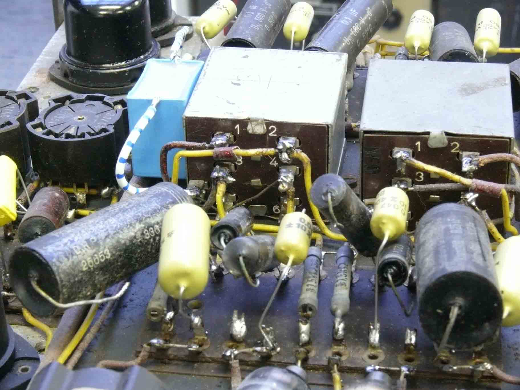
Tracing the route of the 'order' servo connections. A servo (Drehfeldgeber) is having a three phase stator supply and the rotor acting here as a goniometer search-coil having two connections. One signal is belonging to channel A and the second to channel B
My next step was tracing the route where the rotor signal of the order servo is going to

The three connections connected onto a-b-c of the 'order' servo (please consider page XXXV of the Survey report)

The two attached transformers are providing the three phase signals for the 'order' servo
Both fed from a push-pull like circuit, driven by the double triode EDD11

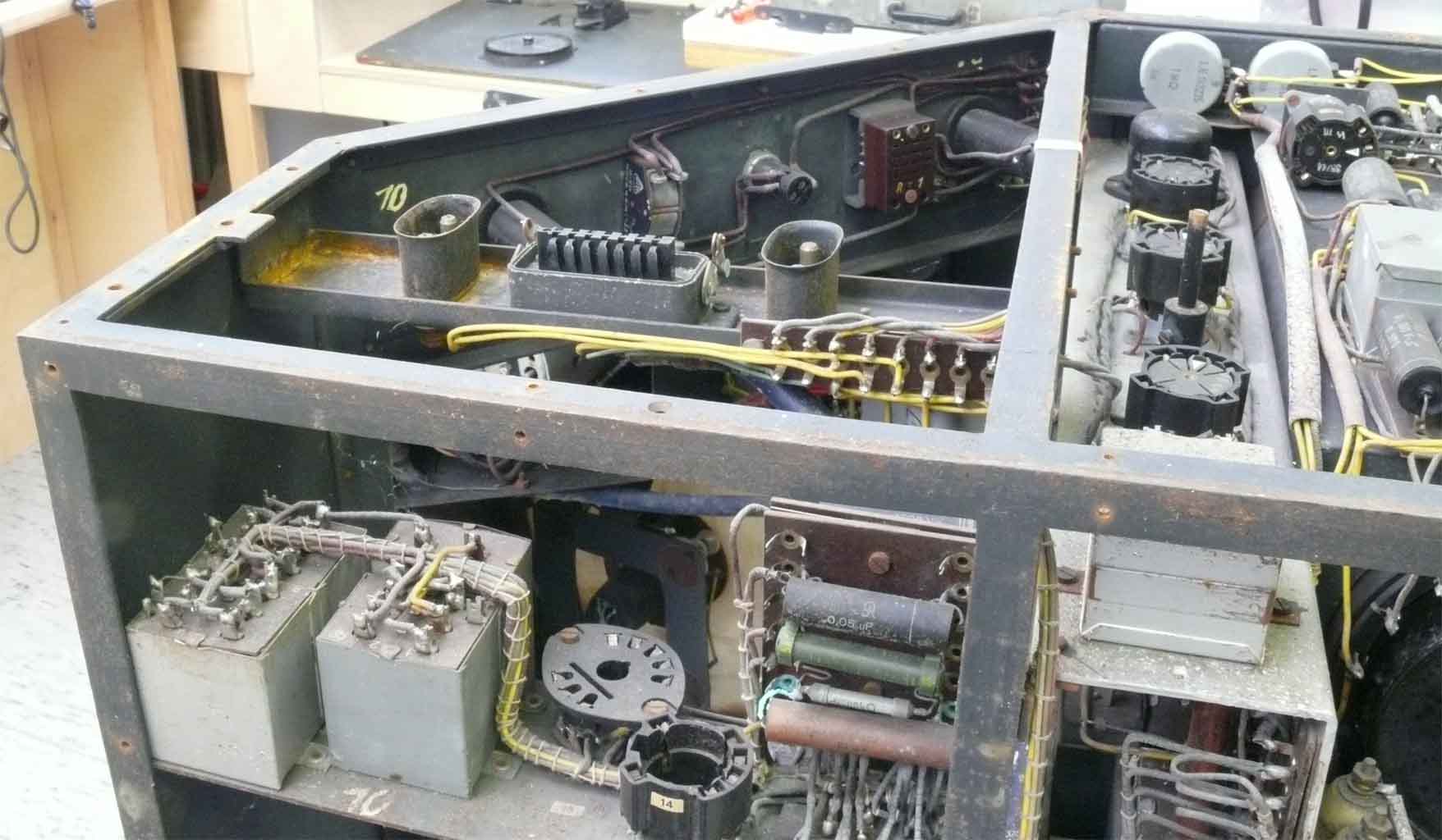
The white-blue wire in the forefront is the bridging wire as to counter the 'sabotage' probably committed about the aftermath of the war. The four connections in the centre the most right one is the one coming from the 'order' servo rotor-coil. After amplification it arrives at the data output stage
This photo is also showing the difficulties encountered where we have to access this section. Tracing the wiring sometimes is impossible!

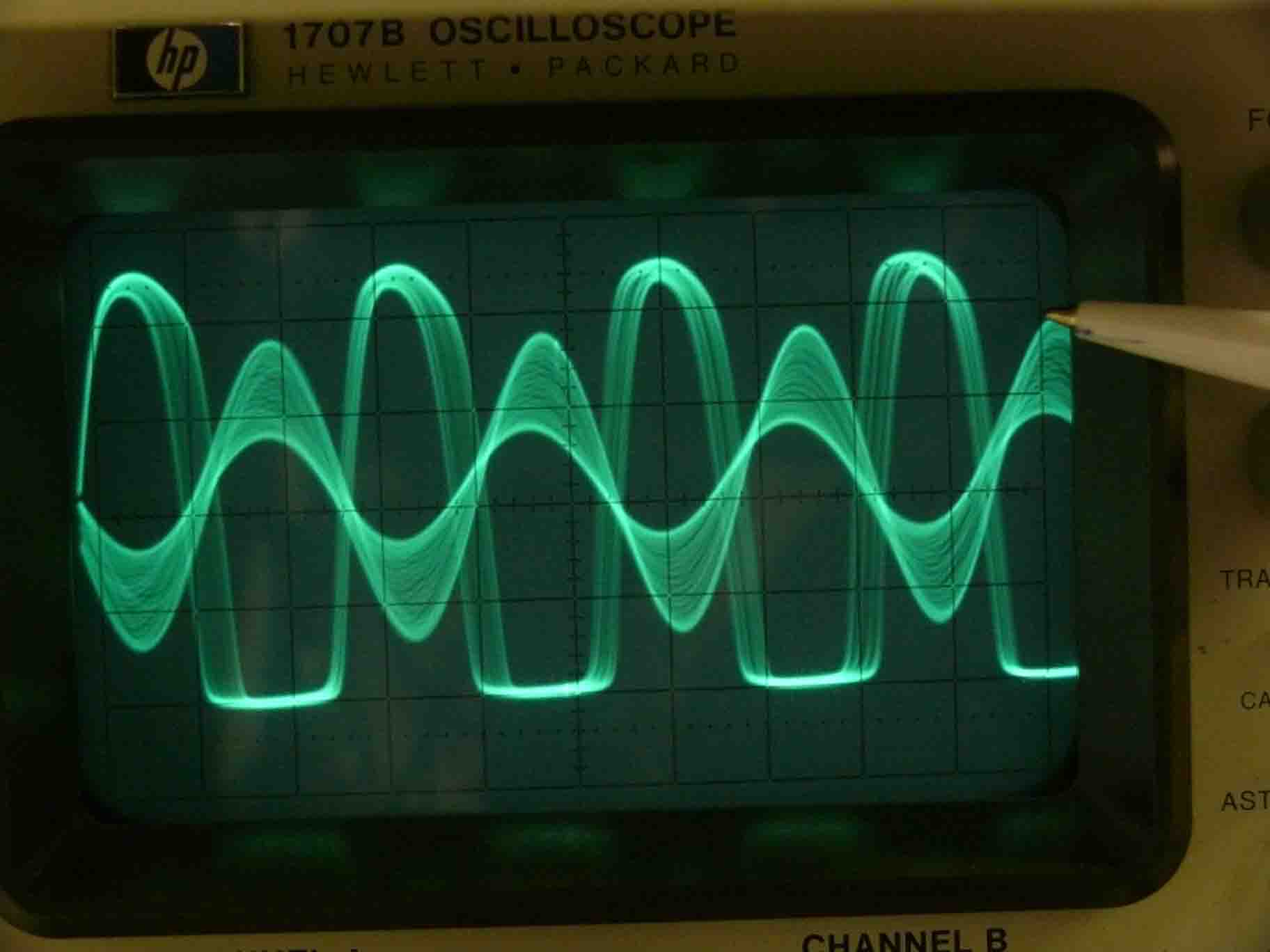
Not directly visible when you view the signal at a faster time base frequency; where it looks like a clean sinusoidal signal (The lower frequency component, was in a later stage of the project vanished)
What is shown here is the actual "Freya-Polwender" output. Maybe is Polwender output not expressing it correctly though, this is the way it is designated at the Nachtfee front panel. 'Polwender' only means that the two output wires going to the Freya- or EGON system is being interchanged. What I realised, was that this makes only sense when there exists a sort of coherence between the 'Impulse' signal fed onto the Nachtfee apparatus and its data output.
It was found that a phase relation exists between the Nachtfee data output signal and the edges of the pulses at the anode of Rö9

Comparing with the previous photo, it is clear that the sinusoidal like signal is being changed in signal phase, caused by a vector change of the 'order' pointer
This is for us the first proof that the 'order' servo is influencing a component of the output data.
Being alert for another acts of sabotage, my attention was drawn to two mysterious solder-tags, which had been once soldered upon.

The soldered tag is clearly recognisable. The screened signal cable originates from the control marked 'Impulsamplitude'. Thus from the incoming signal line

The second solder-tag in the same stage is visible in the lower background
After having experienced a kind of sabotage twice, my suspicion was on higher alert. I wondered already for some time, why is there no sign of locking effect between the external pulse signal what so ever? There must exist a missing link that was certain for me. But how?
My next move was simply connecting a capacitor of 0.022 µF at the g1 connection of the video amplifier EF14 (the open solder tag) and watching what happens at the screen when various points were connected upon. I understand now also why the input circuitry of the EF14 is not having a cathode resistor as to provide automatic grid (g1) negative. It is being operated in class C, where the grid current is provided by the remaining resistance against ground of the input signal divider (potentiometer). This circuit is also causing a square wave like video output signal.

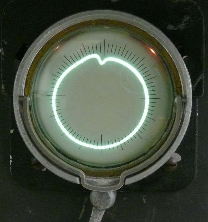
After some experiments this is what was shown at the LB2 screen, when the small 'order' pointer is set at 'North'
The what I call 'number scale' servo is visible on the left hand side of this photo. Its function is, to bring in concert the 'order' pointer setting and the 'order' vector painted at the control CRT (LB2) manually. This may have been one of the objectives of this control screen. It doesn't inflict with the wanted order, as it is assuring that what is pointed is correct; and is equal to what is to be transmitted towards the aircraft under guidance.

'Order' pointer set at East (O)

Pointer set at West
It is evident that there exist a synchronism between the setting of the 'order' pointer and what is shown at the control CRT LB2
Now I instantly realised that the impulse signal provided onto the Nachtfee apparatus actually has to be the repeated signal coming from the Freya/EGON system! Because this is containing complete synchronism with the Nachtfee data output (coherence).
I firstly tried to interconnect the Nachtfee data (Freya-Polwender) with the impulse input. This failed, I guess due to the fact that the output data not matching. Either because the sinusoidal character of the signal or the data output voltage is too low. As to overcome this downside, I connected a capacitor (0.022 µF) between the anode of the data output valve (Rö11) and the impulse input of Nachtfee.

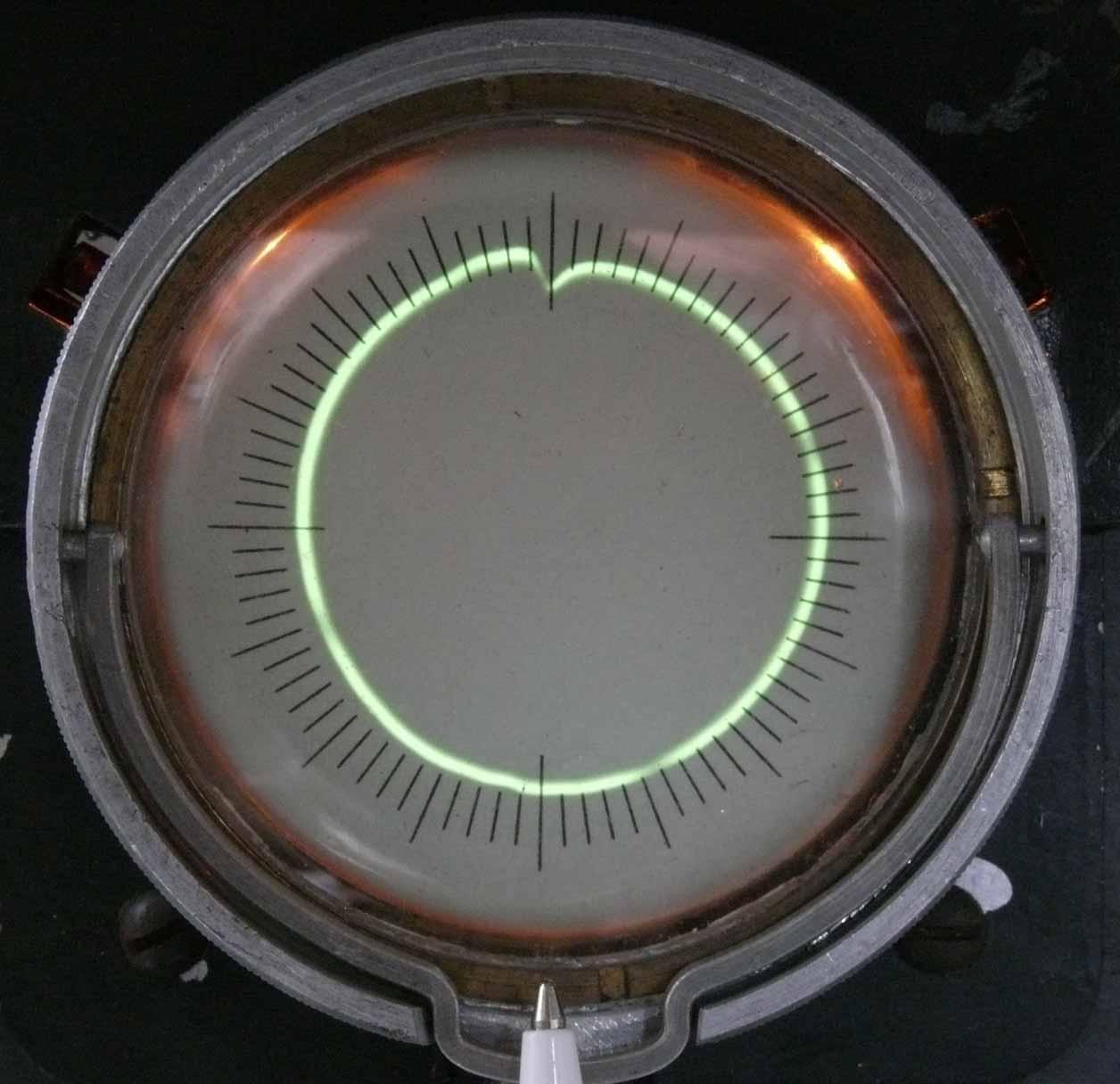
The painted information (signal) is proving that my estimation is correct

The notch now clearly pointing equally at East (O)

Notch pointing South in concert with the 'order'
 \
\
Both pointing South-West
Pointer and notch staying in concert
I strongly believe, that the distortion of the painted line is only due to the way I provide the input signal.
To enhance the understanding of what Nachtfee was about including our recent success in turning it into a sort of working apparatus, I have adapted figure 6 of Radar News 19 (translation of Funkmessnachrichten of 25 February 1945)

I trust that this line drawing is self explaining
Fig. 6 has been modified in respect to the feedback of a controlling signal, which equals the Nachtfee data output, albeit, is being delayed in time.
What is intriguing me, is the attached information: Range adjustment tube. What does this tell us? We are, to our understanding, dealing with two signal lines only. The output data originating from the 'order' or command signal and the system feedback originating from the Freya/EGON system. Egon is allowing measuring distance, albeit, with far less accuracy, on the other side, its measuring ranges is exceeding ranges of up to, say, 250 km!
I cannot yet oversee the implication of this information. As we have already pointed, this drawing, very most likely is, at least partly, not of German origin; but I guess, the result of PoW interrogations combined with Allied intelligence information (like A.D.I. etc). We may estimate, that when Germans are dealing with a drawing in their text and several pointers are used, that some explanation will be implemented in their description.
My first thought was, they have not well grasped the available sources of information. Though, as nearly every aspect of Nachtfee turned out to be different than is thought, it has to be kept open for while.
However, getting it finally working was only possible after was understood that a data-signal feedback is essential. How this will fit in to 'range measuring' can not be answered yet.
As far as is understood - there is only a single data-output and a single feedback signal. EGON range measurement is possible by means of the returning signal coming only, (originating) from the FuG25a IFF transponder. Would it be possible to handle this fluctuating signal in respect to amplitude and two times passing through a wobbled receiving system?
It might be worth giving it a trial. We need a Q-Sender (KUH) - FuG25a transponder - Gemse receiver and a long distance between them. All three device are in our collection, but putting them in operational order, requires different means.
It might be worth, at least doing experiments in a laboratorial environment.
Have we accomplished this Survey? Definitely, not!
Still many questions are remaining. In a non alphabetic order:
Designing an amplifier and signal processing (external) module as to create a signal which can be fed successfully onto the Nachtfee input, as to simulate what might have been monitored during wartime days.
Investigating why only a single quartz oscillator module is working and all the rest refuse doing so.
Investigating why they have used a double beam CRT and why its signal is not responding as expected.
Getting the internal power supply working again.
Preparing block schematics and that like.
Maybe, as just discussed, setting up a chain where FuG25a and Gemse is linked in the feed back chain of Nachtfee data.
Do not forget taking notice of my hand written notebook report
On Wednesday 12 January 2012
We continued with investigating the many open technical question
First, I wired experimentally an EF14 hanging in the air at its wires, as to amplify the Freya-Polwender output signal. Using no automatic grid circuit (cathode directly connected onto ground). Anode resistor being 100 kΩ and screen grid 120 kΩ. Very basic circuitry. My aim is to get a square wave like signal, which afterwards is being differentiated. Although, my first test was not having this latter network yet.

LB2 showing the not yet differentiated signal

LB2 signal equal as the previous one, though, 'Freya-Polwender' switch being used. Causing a 180° (π) signal shift at the Nachtfee data output. North rotated to South
The square wave signal is what is available at the external EF14 stage, originating from the Nachtfee data-output. The smaller square wave originates from our Wavetek generator.
The EF14 signal is normally triggered upon, whereas the Wavetek signal is running freely.

Comparing both screen shots one might think that the Wavetek signal has changed, but it is the Nachtfee data-output that has changed its signal phase, after the 'order' pointer was set differently. Why we think that it looks like differently, is caused by the fact that the data output is triggered upon
On Hans Jucker's request, I measured the data output frequency; it proved to be about 520 Hz. Its frequency drifted a bit downwards over a bit longer period. Curious was that we previously have noticed that a single pulse is being painted at the LB2 CRT when we feed Nachtfee, via the Impulse input with a square wave having about 260 Hz. In some respect both figures coordinate as 2 x 260 makes 520.
During the course of our investigations, I also measured what the effect upon the data output frequency versus quartz channel change is. I measured about 0.9 Hz. Although, one might have expected about 4 Hz (between channel 3 and 4)(please notice Survey report page III). Whether I made a measuring fault is not yet clear. I encountered serious problems with measuring Nachtfee signals precisely. As to counter problems, I came up with the idea letting the scope triggering upon the Nachtfee signals and the second scope channel was being connected with our Wavetek signal generator. Which output frequency was checked precisely by means of our DANA counter. I calibrated the start of the Wavetek signal edges exactly in concert with the Nachtfee signals. It might sound a bit clumsy but it works and is not causing ambiguous errors.

We are looking at both CRT displays. On the left the AEG double beam display. On the right the right the LB2. Both showing what occurs when the 'order' pointer is set at North. The two traces left are likely looking in a sort of complementary way

'Order' pointer set at Ost (east). The LB2 display (right) is staying in concert. The two traces on the left a showing their mutual phase relation. Why this is done this way is not understood (yet?)

Pointer is set a South-West.
LB2 control display pointing North, showing the experimentally differentiated signal (feed back)

LB2 showing what happens when the 'order' pointer still is set North but the Freya-Polwender selector switch is operated. Causing a 180° (π) Nachtfee data shift
The projected circle is a bit too much out of centre; why is not yet clear, as the controls are no longer allowing enough vertical shift.
During the course of our investigations yesterday, we encountered some problems. We tested what the influence of changing from quartz channel 3 to 4 and inversing. The oscillator inside the what we call double sized module, where the about 970 Hz signal is being generated. The system started like 'motor-boating' when a quartz was switched on. It ran quasi normally without quartz signal. It finally proved that its free running frequency was a bit too high. Lowering it a bit and things run as was before. I also discovered, what I apparently didn't have grasped when I looked at it before (MLK). At page X in my Survey progress report I didn't realise, that Rö17 acts as a divider 1 : 5. Thus its output signal is at about 3 kHz. The next stage Rö18 was well recognised being a frequency divider, but did not realised it acted 1 : 3. I understand now why the andode signal of Rö17 looked so complex, it contains two signal components!
My next move was looking more in details into the double beam CRT circuit. Their existed a large amount of tendency of time base deflection jumping caused by light vibrations and mechanical touching. After pain striking trials and errors, a very small piece of wire was found that it was poorly soldered at both ends. I do not think it was deliberate sabotage, although, the next transformer in this stage was doubtless being sabotaged.

Viewing the deflection section of the dual beam CRT. Om the left hand side, we see the coupling between the video stage and the vertical CRT deflection. The blue coaxial cable is feeding its signal onto the LB2 control display
On the upper left hand side of the adjacent chassis section (a bit north-west of the two deflection transformer) we see the Nachtfee data output transformer (Freya-Polwender signal)
On 13 January
About a week ago Hans Jucker and the author of this webpage discussed how synchronism might have been accomplished. I came up with various ideas. All more or less outside reality. Until a brainwave told me that there exist a simple means.

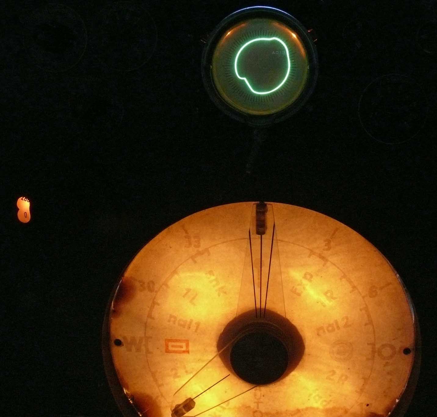
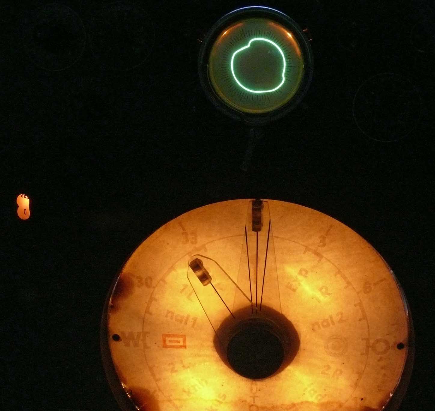
In page 3 we have already dealt with the fact that of the two compass pointers only the small one is actually linked with a servo (Drehfeldgeber or selsyn); it is only spring-locked at its 'north position', shown in this photo. The adjacent disk is having a range of notches at every particular order setting (shown below)
Because the small pointer is the only one effecting Nachtfee phase shifting, the large pointer I never used and is kept (randomly) in the north position. When an order is being selected, it is likely that the operator turns the small pointer hair-line in line with the larger pointer. Whether the two hair-lines left and right off centre implicate that there is to be adjusted with this arc sector I do not know
What is more likely than that the 'order' pointer is always starting from north position? This is then also conveying the north setting (marker) at the display screen in the aircraft cabin. This is, of course, my guess and might be refutable. Bearing this in mind, Trenkle's explication is coming a bit more in line. The way he described it, one gets the feeling that he didn't totally grasped what it actually was about. He was simply lacking any form of technical documentation, apart of his ominous source reference [101], being the Felkin report; which is so far not been found integrally. (notice the Nachtfee introduction page) (In the meantime we have found them, it constitutes a pile of 1000 reports!!)
There are still a range of open questions remaining.
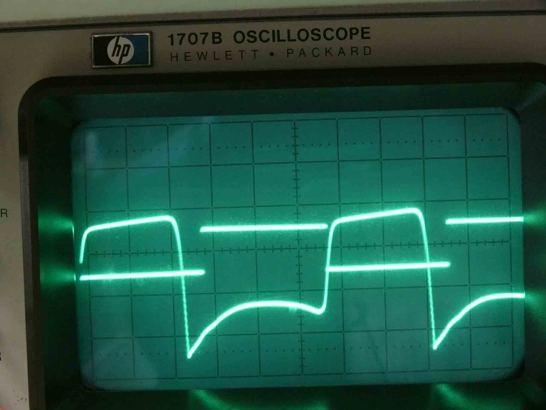
This screen shot is showing the distorted Nachtfee data signal, after it has passed through a saturated EF14 valve stage. This stage is experimentally kept outside our Nachtfee unit (amplifying the Nachtfee output signal and providing an adequate input signal for the feedback line (My designation: controlling signal)
However, this signal is giving, after first order differentiation, quite small pulses mostly of a negative nature, containing however, also some minor positive components. When we tune the input potentiometer (Impulsamplitude) accordingly, the weaker pulse component is hardly visible at the LB2 screen. It is, nevertheless, possible to eliminate them, but as they are not crucial for our experiments I would not like spending too much attention on it.
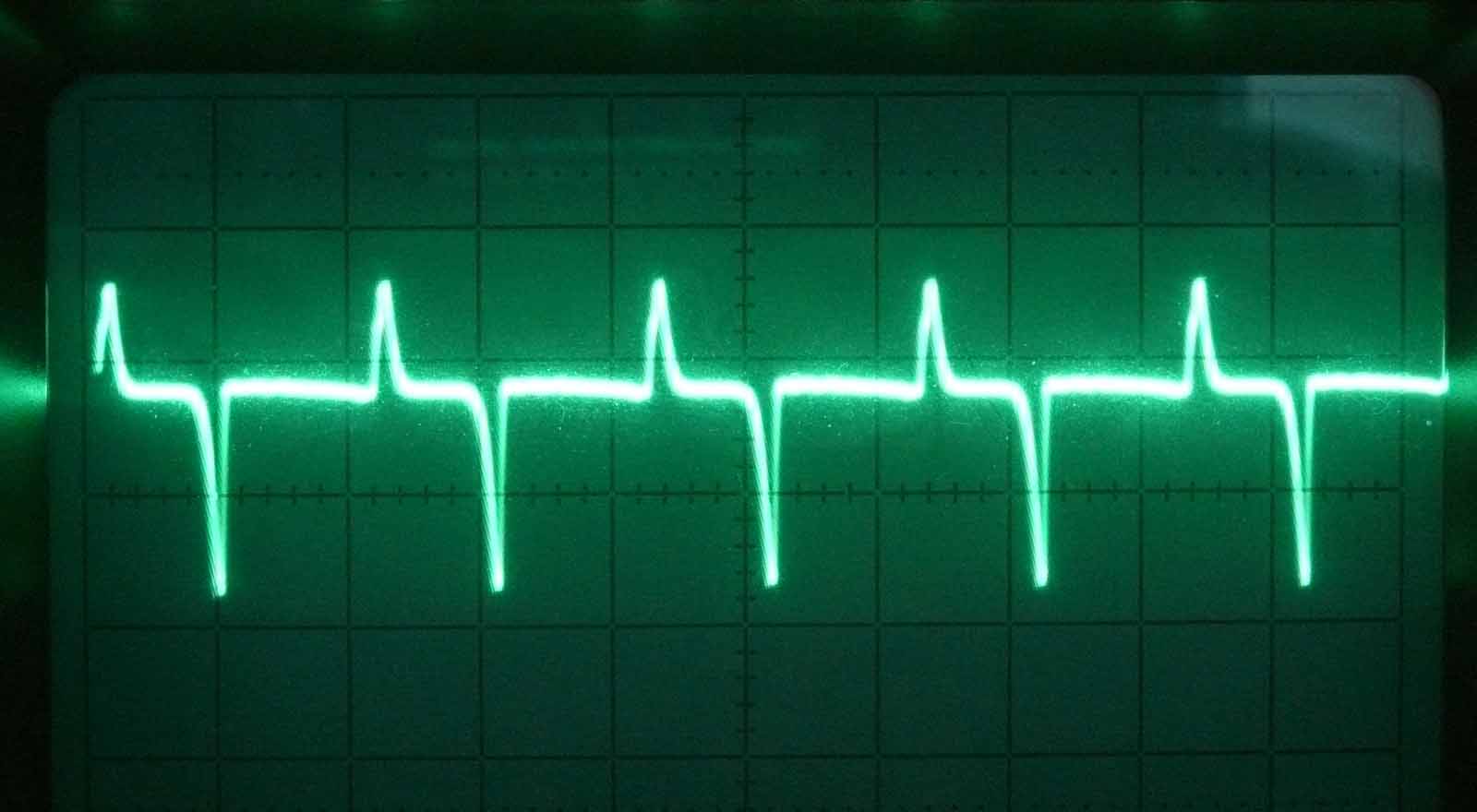
Pulses measured at the pulse input of the Nachtfee apparatus, after simple first order differentiation. Signal phase rotated 180° (π) between data output and pulse input, due to the insertion of an additional (external) stage (EF14)
My estimation is, that this might have been done similarly for the aircraft display unit. Using for circular deflection the sinusoidal signal component for synchronising (keeping it in concert) the circular deflection of the aircraft CRT, while the small 'order' pointer is set north. Phase shift only occurs when the 'order' servo is being operated.
Would it have been possible keeping the aircraft display system staying in concert with the main pointer setting, thus when it is kept in its 'North' position for a period of time? My guess is - maybe technically possible. Another guess, it might have been accomplished by using a flee-wheel circuitry. Not fully understood, is how they could cope with the data frequency owing to a selected quartz controlled channel. The accompanied airborne technology must have been not too complicated, as the total airborne system weight was 12 kg only. These figures often include also auxiliary systems.
This aspect is very significant, as the quartz controlled channels (selecting a single one out of ten) is changing the data-output-frequency slightly; as far as we could notice (measure), a few Hz only.
On 13 January 2012
I continued with my investigation
As usually, when a new visitor is around, "Murphy" was also about (Friday 13th), and some section was not responding as it usually does.
It proved, however, that a wire would resistor of 2 kΩ caused problems again. Why I had disconnected the bridging resistor I cannot remember. The HT increased from 30 V to 170 V. Since the stages work as expected again.
My attention was drawn to the quartz and the attached double sized module. I decided trying to get some more quartz oscillator modules in working order.
What was already expected, these modules all differ a bit in respect to their critical components and wiring. This may indicate that they have faced this nuisance during wartime days.

In the meantime we managed getting the 'Frequenzkontrolle' functioning again by means of contact spray. (checking the working order of the quartz channel signals)

The same type of quartz signal, but now painted at the LB2 control screen
This is a very helpful test button, as it shows the behaviour of each of the 10 quartz signals. Their starting up response is clearly visible. Each quartz module is provided with a potentiometer allowing individual adjustment. That these oscillators are starting up quite slowly is very good recognisable; which is very significant, as its quartz vibration can destroy the quartz bar easily (longitudinal X- mode vibrators, having Q-factors >100,000)
However, I replaced in all modules the critical failing capacitors of 0.1 µF and an electrolytic capacitor of 25 µF. I decided to remove the latter totally, as their acid leakage is causing heavily oxidised wire and solder-contacts nearby.
This is confirming the fact that some modules can operate at certain quartz channels and is refusing so when operated in some other slots.
It was found, that the channels Q1 and Q2 can be activated though, the about 970 Hz locked signal is jittering. Maybe, Q1 sometime gives the impression that it would lock upon, but I still doubt that it is doing so appropriately. (Please consider for the accompanied quartz frequencies my survey report page III)
Reliable operating is now: Q3 - Q4 - Q5 - Q6 and Q8. Whereby Q5 is in the spectrum centre of 15000 Hz. Easily can be found, without a table, that Q4 = 15000 - 60Hz = 14940 Hz and that Q3 = 15000 - 120 Hz = 14880 Hz and that Q8 provides 15180 Hz.
Why not giving it a try and measuring the recurrence frequency of the differentiated pulses?

Selected channel belonging to quartz 3 (Q3), pulse is adjusted at north

Q6 being selected

Q8 channel is switched on. Vector rotation anti-clockwise is clearly recognisable
(using my pen is allowing me to point what photo is belonging to which observation, as sometimes more than a single screenshot is taken)
I also measured their according data output frequency
Q3 caused an output frequency of 496/7 Hz
Q8 provided an output signal having 506/7 Hz
Thus between 14880 Hz and 15180 Hz the Nachtfee data-output frequency increased only about 10 Hz.
I do not understand fully how these figures should be interpreted; and what its operational implication may have been.
My first thought was that the vector deviation is relatively small. Maybe time will allow us judging how the various parameters were interacting operationally.
On 16 January 2012
I continued the survey
My first step today was modifying the remaining quartz modules. During the course of doing so, I encountered that stage Q1 and Q2 were still not stable locking onto the Nachtfee system. Some time ago I encountered forms of what in the old days was called: motor boating. An old trick is increasing the HT voltage and it helped for a while (and increasing the value of hum blocking capacitors).
Why not increasing the supplied HT onto the quartz as well as, which I have designated: Double size module? I did so and Eureka, the Q1 and Q2 quartz channels locked properly.
The next step was also found that from now on this module provides an about 1000 Hz signal. Which was clearly locked upon when a quartz channel was operated.
Q1 provides: 985 Hz signal output (Double size module) Maybe 984 Hz
Q2 provides: 988 Hz
Q3 provides: 992 Hz
Q4 provides: was by then not yet operated, referering to the 4 Hz steps 996 Hz
Q5 provides: 1000 Hz
Q6 provides: 1004 Hz
Q7 strikes
Q8 provides: 1012 Hz
Q9 strikes
Q10 strikes
Viewing this list, it is clear that the 60 Hz quartz channel separation is after division by the ratio 1 : 15 providing locking steps of 4 Hz (4 x 15 = 60). Thus the Nachtfee data-output will have 2 Hz step separation (for each successive quartz channel).
This signal is after leaving the double sized module fed onto the circuit about Rö1 and already at its anode we could measure a 500 Hz signal. It proved to be impossible deducing the circuitry around Rö1 and Rö2. I have to live with it, there is no other way; as the wiring space is too compactly constructed.

Part of the hand drawn schematic of the 1 : 5 frequency divider incorporated in the, what I designate, Double size module (my survey report, page X)
On 31 January I received a response from Bernard Gele from France, who sent me the following link
Bernard referred onto it that it concerns a "regenerative divider", in the previous file it is also called submultiple frequency divider. This sounds rather logical to me. By the way, a good paper!
It is in those days a well known technique, by which means a frequency was divided. Rö17 acts as an oscillator tuned at a lower frequency. It should, however, be tuned at about n = 2,3,4,5 ... In the Nachtfee circuitry they used three dividers of this principle. As to get 500 Hz synchronised signal, divided in two steps, first by a factor of 5 and then by 3; resulting is 15000 Hz : 15 = 1000 Hz. : 2 = 500 Hz
When we started our Nachtfee survey, I measured about a 970 Hz signal, which might have been caused by the fact that locking conditions was not (yet) appropriate. Looking back, an explanation may have been - that the Double size module signal was not yet loaded by the rest of the Nachtfee circuitry. Also by the circumstance that my first test in the MLK lab. was accomplished by a single and later on two quartz modules only, whereas we now deal with 10 quartz modules. Their outputs are wired in parallel and being selected by means of a switch. Though, oscillators are running continuously all the time. But their screened output cables are actually constantly loading the input circuit of the Double size module. That there exist such an influence is faced as after nearly all quartz modules were put into their slot the appropriate locking signal at say 1000 Hz is measured. However, as we have discussed previously, system stability has increased also by means of increasing the overall HT supply with about 20 V.
Although, probably meaningless, I also investigated what occurred when:
When North is adjusted onto the application of quartz channel 1 (Q1)

This time channel 8 (Q8) is selected
After a vivid exchange of thoughts, Hans Jucker pointed that we may have to deal with the fact that Freya in some way had been involved. We know, that EGON system relies on Freya like techniques, though, is not operating the regular Freya transmitter/receiver; but is exploiting the IFF transponder FuG25a (Erstling) in stead.
Viewing the selector switch available at the Nachtfee front panel which informs us: Freya-Polwender" we may not have considered a two way system implementation. Freya combined with EGON. In this respect the Radar News 19 Fig. 6 drawing is showing a Freya like station, albeit, exploiting the FuG25a IFF transponder. Visialised by the small vertical antenna rod just below the aircraft belly .
The existence of clear quartz stabilised (synchronised) channels at about 500 Hz, is pointing in the direction of exploitation of Freya combined with EGON, as both may have employed a 500 Hz system frequency (prf).
We know that Freya was equipped with a rather accurate delay-line, by which means distance of particular target was measured. It used a mechanical, quasi digital, read-out. The range measuring unit is known as Z-Gerät (Jagdschloss Freya and Seetakt). Please notice Hans Jucker's brief concept, based on the system layout of Jagdschloss. The wave form of the returned Nachtfee information may differ, as the lower spectrum signal component we cannot visualise any longer (was maybe a kind of hum). We now think: that the Z-apparatus may have been used for both Freya as well as EGON operations (albeit, the latter having accuracy limitations and there must be dealt with an additional off-set lag of say 400 m, at least this was the case in conjunction to regular Freya-IFF operations). My guess, EGON (EGON-B?) will encounter similar system time lag.
Another implication dealing with is the feed back or controlling signal that was picked up (provided) from about the IFF transmitting stage. Whether directly or indirectly by means of a separate small antenna somewhere near to the transmitting IFF antenna, I don't know. This may sound curious, but was similarly used in Seetakt; in conjunction to the Gema X-Gerät. More likely is that the data modulated output was provided directly from the IFF transmitter stage. Of course, still being my assessment.
The shape of our Nachtfee apparatus discussed before, points strongly into the direction that the Nachtfee consol was installed more or less adjacent to the regular Freya/Egon control units, thus kept in the same operational cabin. Why would they otherwise have shaped it this way? Please bear in mind: photo 1 and photo 2 . Paul Reuvers pointed, that this shape reminds him that it was providing a path (way) for operators. It is known, that some of the Freya cabins were quite crammed, and that sometimes first another operator had to clear a way for another colleague. However, whether this actually was the case in our Freya/EGON (operational) cabin, I do not know.
Significant for us is to get more detailed technical information on Freya and/or EGON. We have not yet been able to trace such kind of technical documentation. Phil Judkins helped us with finding some PRO/NA files, but these are so brief, and hardly technical, that for this survey these are meaningless.
Is there someone around, who would like to participate in this Nachtfee Survey Project? Please contact us at:
![]()
And type in what you read
Those participating will be recognised and fully referred on to.
It first is necessary to replace the Freya-Polwender switch, which has a broken handle. Very hampering, is that the space around it is difficult to access. A second downside is also the fact that its wiring is kept rather short, thus proper selector replacement will encounter quite some problems.
A future point needing our attention: what is the influence of the comprehensive thermostat (60° C, controlled by a mercury thermometer with Pt contacts) in conjunction with the quartz oscillators? May this having influence on the activity of the quartz crystals? Would it be possible, that the three striking quartz controlled modules will become activated as well?
Another thing which has to be accomplished, is getting the two internal power supply systems operational. It proved, however, during the many experiments, that it was found very conveniently that the HT could be switched off (300 V and 1 kV) while the 220 mains supply was kept on working (filaments kept running). So that all worked instantly after HT was supplied again. I believe, that two switches should be build-in additionally, which allow switching off at will.
Remounting the cover plates, and maybe doing some other work necessary.
On 18 January 2012
We continued our Nachtfee project
First I would like to come back on the problems faced in respect to getting the quartz modules in a working order again. As have been pointed before, the Germans must have faced this nuisance already during the war time days. At these very low frequencies (here being about 15000 Hz) the condition under which quartz vibrators have to operate is rather different compared to high frequency piezo-electric vibrators. Their spectral bandwidth is extremely narrow. Second, oscillation occurs in a positive feed back system. As long as there is no signal there doesn't exist a feedback signal. Omitting the switching-on effect which apparently doesn't have any influence upon starting up of these low frequency oscillators. Now the limits of nature is helping us - as every component in the chain create a certain amount of noise (valves, but also transistors, also resistors). Noise is a wide spectrum phenomenon, only when at the right moment enough noise is entering the small band-pass of a piezo-electric vibrator a signal is becoming available for eventual positive feed back. Normal quartz vibrators are starting up virtually instantly though, very low frequency quartz do not respond this way. The Nachtfee control button is visualising at the CRTs how slow their quartz vibrators are actually starting up (sometimes taking a second or beyond!). Another point of concern, is that the Q-factor of these quartz is extremely high we have to count with: 100,000 and beyond. When such a device is excited without precautions, it will destroy itself instantly. A Q-factor is a multiplying factor as well, beside the fact of remaining its state of excitation for a while after being switched off. Our ring-quartz experiment (at 375 Hz), demonstrated during the Kootwijk Event of 2000, proved that when this quartz runs normally its gap can be widen up an additionally > 5 mm! We could demonstrate this phenomenon, because we watched it by means of a stroboscope, where it is possible to visualise the gap at any instant. Thus extracted (open) and when it is contracting (and, of course, in between)

Clearly visible is that the box has been opened before
Viewing the implementation of an additional capacitor (50 pF) just visible from the top having the quite long open wire end. This was one means of improving the ability to oscillate. However, we know now that Q6 channel can be operated, thus they have cured it in the right way. This may also have been the reason why they used channel numbers on each individual module. I encountered that some were working normally when operated in their according slot, but sometimes strike in another slot.
As have been mentioned in the last four points, we should dedicate our attention towards getting the Thermostat working again. My first step was simply supplying 220 V ac (via a transformer) and watching whether two thermometer contacts were responding after a while. Some small voltage was measured across it , but the only thing it really told me was that after a while of heating - it dropped to about 0 volt. (thermometer contacts closed by the mercury column of the thermometer)
With some imagination the relay socket marked R1 is recognisable, just north-east of the right power connector meant for the Thermostat power (220 V ac). The centre multi-contact connector is the so-called 'List-Stecker', which provides data output as well as impulse input (feedback or controlling signal)
A problem was, that already someone in the past must have removed a relay. Its base is similar to the well known Siemens & Halske polarity relays, applied for teletype and repeaters. These are very fast responding and could even be operated practically at 50 Hz and beyond. After I had followed the wiring, I decided to give it a try and simply taking such a relay from our stock. I choose the type which has a clear plastic cover, so that operation could be watched. As to interfere in its operation, I removed the cover first so that I simply could watch what happened when the centre contact was manually operated. It worked instantly. I now supplied 220 V ac via the Thermostat mains connector. It was, however, inserted a current meter as to notice its actual current consumption. When it is heating it takes 0.15 A, when oven heating is off it consumes only 0.02 A, equal to a power consumption of maximally 33 W.

The Siemens 'telex type' relay is good visible
It finally was necessary to increase the free space between the centre contact and the two outside contacts a tiny bit. Both are visible in the previous photo. It was found that the Thermostat is operating when the relay is in its non activated state. Only when the mercury thermometer contact is closed (at 60° C) the relay is activated.

Thermostat is temporarily switched off

The Thermostatic oven is being heated
The thermal insulation of the thermostatic oven makes its outside only lukewarm. The quartz compartment is kept at 60° C (according the information printed on the Q/K quartz housing).
In the meantime, when I was working on the Thermostat, Dick Zijlmans was replacing the "Freya-Polwender" switch (broken handle). As was already expected, a quite difficult undertaken, which is successfully managed. Dick told me that both switches (the original and the post war one) were originating from the same manufacturer). One may wonder why this was so difficult? The reason is, that its angle plate is fixed by means of two non-accessible 3 mm screws. This is a fundamental nuisance, as all transformers in the left and right hand section are fixed this way. The mu-metal crt screen is preventing its access. Removing it is rather difficult as it forms in some respect a unit with the double trace crt socket/base.

Freya-Polwender switch, which only interchanges the two output wires of the Nachtfee data-output
However, interchanging the two output wires can only be noticed as long as there exists coherence between the Nachtfee data-output and the feedback signal. Causing at the LB2 CRT screen a 180° signal rotation when the switch is operated.
I believe that we have to accept that quartz channels Q7 - Q9 and Q10 will not become operational. I don't like to dismantle the complete quartz and mounting module again. It is, in my perception, not essential for what Nachtfee is about.

A typical laboratory set up, we measure the Nachtfee data output frequency which is measured at: 500.088 Hz. For this occasion Q5 (15000 Hz : 30 = 500 Hz). As to preventing damaging the counter input section, signal is picked up by means of a 1 : 10 scope probe
Nachtee divides the 15000 Hz (and adjacent quartz channels) by means of three synchronised stages: 1 : 5 then 1 : 3 and finally 1 : 2 (please regard also what is mentioned in the 16 January 2012 section).
On 25 January 2012
We continued with:
Replacing some of the blocking Cs by more appropriate types (2µ2 instead of 1 µF types).
When Dick Zijlmans arrived, who brought very kindly an EZ12 rectifier valve because we have only a single one in stock, we could give it a try getting the Nachtfee power supply operational.
However, both valves constitute in Nachtfee a single phase rectifier each (where both anodes per valve wired in parallel, as to cope both with the increased current consumption) This resulted in an enormous increase of HT voltage, it proved to be about 440 V!
Though, this high tension increase solved all previously encountered side effects, like 'motor boating' and other means. They used a so-called "swinging-choke" just from the rectifier cathodes. And, the first blocking electrolytic C is after the swinging-choke. The reason for doing this, is to stabilise (smoothing) varying loads effects. However, for security reasons I implemented an additional fuse (315 mA), as our Nachtfee apparatus does not have one, beside the main fuse of 4 A. Before this is blown-up the power consumption should pass 880 W, which is long after the HT transformer is ending up in smoke!

The newly inserted pair of EZ12 rectifiers
Comparing the A-scope channel signal of the 'c' servo- goniometer contact in the far background and the feeding end of the cable by means of the B- channel (green test cable). I must honestly admit, that I never expected that it was originating from there! Looking back it is now becoming understandable.
The red and yellow test cables are supplying the about 1 kV for the CRTs. This must remaining for a while, as long as the failing HT transformer has not been repaired.
Tracing some of the circuit, as already mentioned before, is often rather difficult; sometimes even impossible. In particularly where the circuit is hardly accessible, which often is the case.
It was found for the first time in detail, that Rö8 (EF14) from its anode side is feeding the central deflection stage of Rö12 and Rö13.
For the first time, I dedicated my attention finding out from where the the "number or scale" servo is getting its signal from. Un-expecting, I discovered that this signal originates from the EL11 power deflection circuit (using the method by two chopped scope channels, of which one is connected onto the servo-goniometer and the B-channel is looking for a signal match in phase and amplitude). Please view the previous photo, where the green test-wire is contacted onto point 'c' of the number servo- or goniometer. Again fed from, as all other two servo like goniometers, by means of a two transformer arrangement. Its search coil (rotor) is fed onto the central 4 pin solder strip of the right-hand chassis (watching from the front). Its signal is then fed via a transformer onto g1 of Rö9 and from there onto g1 of Rö8. Rö8, is supplying the central chassis section (deflection stage). Which is a kind of push-pull system, or at least a sort of symmetrical system.
Please consider my Report notes.
It was also confirmed, that the "Phase" servo-knob is within the main signal chain from the quartz controlled Double sized module, divided by two (1 : 2) in between Rö1 and Rö2 and finally fed onto Rö3 (EDD11). This push-pull like circuit, again is having a pair of transformer which supply three phase signals onto the "Phase" servo knob. From there it passes to Rö4 and Rö5 and again is fed onto the push-pull like stage Rö6. Again its output is consisting of a pair of transformers, which provide the three phase signals onto the 'order' servo. Which goniometer search coil is supplying its signal onto most left contact of the centre strip of the right-hand chassis (seen from the front). This signal is then fed via Rö10 and Rö11 onto the Nachtfee data output transformer.
Please regard the: Nachtfee block diagram
We encountered also a nuisance, as it proved that the about 1 kV HT transformer for the CRTs HT is having an internal short-winding or internal sparking. After some troubles Dick Zijlmans managed to remove it from the main chassis.

In the background of the transformer the empty space left after the failing transformer was removed
Just visible is the base of the HT rectifier RFG5.

The corpus dilictum
On 1 February 2012 (Bladwijzer10)
We continued clearing the mall functioning brightness control to the LB2

The failing potentiometer being removed
The top plate had to be removed, before we could access the insulated mounting plate.

As we did not have a 100 kΩ type we used a 220 kΩ one. Which apparently function well
After the cover plate has been brought in position again, Dick Zijlmans cut the potentiometer shaft and fitted all the scale plates and other means.
On 9 February 2012
We encountered some problems, which might have been solved after having extra (newly) soldered all transformer contacts in the EL11 circuit. It was found, that when Nachtfee was switched on, that for a while the horizontal time base for LB2 and the dual beam CRTs were jittering. Which, after a while stops. The Nachtfee data output did not suffer from this down side. It was also found, that during the period of jittering, the 'grade or number control' didn't operate appropriately. That is why I focussed some attention onto this three phase circuit.
Dick Zijlmans took care of the fact that the small left lamp for illuminating the screen inscription of the LB2 control CRT failed, whereas the right one works. Solving this proved, however, being not quite simple. Nevertheless, after some problems it has eventually been solved. These scale lamps are of a special type which are made for 24 V operation. However, all these lamps used in Nachtfee, totalling 13 pieces, are actually being operated at 12.6 V. We may assume, that they will work for ever. Similarly is the case for the RPG2, using the same type at 12.6 V.
All may seem to be hard to understand, but please notice my block diagrams in the Nachtfee Evaluation and Conslusion page (in progress)
Next week we should, Deo volente, investigate whether there exists an influence between the actual phase of the 'order' signal and the 'number scale or grade' control is being operated. My guess, is that there should not exist an influence. However, as so often during our Nachtfee Survey, we may be surprised again.
On 10 February 2012
We continued with preparing the Nachtfee chassis for final fittings.
My first attention was dedicated onto the wiring of the door like section, carrying the LB2 control screen, as well as the 'order' or command compass and the other goniometer controls.
Then, after having switched on the Nachtfee system again, it was found that still the number-servo system was not working appropriately. For the first time, I traced the exact wiring of the number-scale servo input (three phase signals). The details have been noticed in my Repair Report on page 55/56/57 (L V + L VI + L VII).
It was, however, encountered as usually, that after a warming-up period the system worked correctly again. It was nevertheless, found that Drehfeldgeber 'tag a' was having a quite low signal amplitude, which originates from 'tag 4' of the most outside transformer next to the EL11 output valve. This was also the case when all worked appropriately again, thus this aspect must be looked after during another occasion.

The second step this day was modifying the Nachtfee wiring, which has to implement additional blocking (smoothing) capacitors (replacing the unreliable wartime types, the Al tubes in the background). The four replaced resistors are implemented as the genuine resistors was found being burned out. The yellow and red cable is supplying the about 1 kV for the two CRTs, for the time being
This was accomplished by mounting them (electrolytic Cs) on the rear-side of the mounting board. Extra attention had to be made for the main or first electrolytic blocking capacitors (just at the output of the swinging-choke). Originally a pair of 16 µF electrolytic Cs had been used. These are today totally unreliable and had to be disconnected all. As we have operated Nachtfee from an electronically controlled HT power supply, which could with the existing load only provide about 290 V, all worked smoothly. Though, after the internal (original) power supply has been made operational again, we have to deal with about 440 - 450 V. The 68 µF (this is what we have in stock) electrolytic C is only capable of handling 350 maximally. It was thus necessary to wire two equal Cs is series. As to maintain an equal voltage division, we added two resistors in series and connect these at the centre of both elecos.
After the removal of some smaller elecos, it was discovered that a series of them were totally burned out. After first having completed the upgrade of the power supply, my attention was focussing onto what had caused this nuisance.
It was soon found, that the output of the later ≈ 140 V was loaded against ground by an about 880Ω at 'tag 2'. Please notice the wiring between tag 4 to 5 and the most left one, where the white-blue wire is connecting the 2µ2 blocking C. One might getting the impression, that the transformer can had been opened once before
The leaking resistance was connected onto 'tag 4' of the left side transformer. Though, why, is it having an internal short circuit? After elimination of all the possibilities, it was found that it had been my own fault from some months ago. Falsely meaning that a ground-like connection should be interconnected with the one of the right hand side transformer. It became clear to me, that several transformer arrangements always only a single one is actually connected onto ground. Why this is done I don't know. Then I tried to connect onto this soldering tag a capacitor of 2µ2 against ground. Resulting in a slightly improved horizontal deflection of the dual beam CRT.
I do not yet fully understand why, nevertheless, the circuit worked as it did. After having removed the bridging wire, I was heavily disappointed, as there hardly was a visual horizontal deflection left. However, after adjusting the 'horizontal amplitude control' the screen is showing what it is supposed to do. Now the deflection-amplitude-control is working far more effectively than it did before.
On 13 February 2012
We continued with bringing our Nachtfee apparatus into a displayable fashion again
First we remounted the side-cover-plate belonging to the door-like section.

After having replaced the side cover, my attention was drawn towards the way this Nachtfee apparatus had been operated
Please notice the horizontal metal strip having two notches at both ends.

The door-like section is fixed by a vertically locking mechanism
Please notice the handle on the right in this and the previous photo, which has to lock (fixing it) the door in a certain position. It is clear that the door can also be fixed when it is turned to be inserted into the Nachtfee main chassis.

The door locking mechanism, viewed from inside
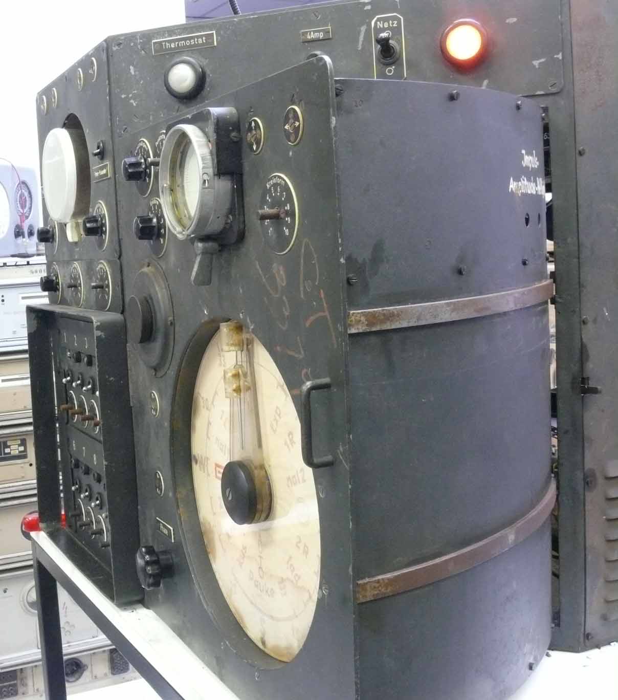
It is evident, that the controlling front panel is now set in an integral flat position
(Bladwijzer32) Next my attention is drawn to the phase spectrum displayed at the dual beam CRT (HR2 ..) time base line. Here only the signal of a single trace is made visible. The second trace is simply rejected by means of the brightness control setting

Shown is the HR2 ... CRT pulse originating from the feedback signal. 'Order' pointer set at North
I have to apologise for that the 'order' scale illumination is kept rather dim

Like above, 'order' pointer set at East (O)
One get the impression that the phase shift painted at the left CRT screen is equal to a 90° (mathematically expressed ½ π)

'Order' pointer adjusted at South. Please notice that the pulse response is rotated 180° (π)

It is clear now, that what is displayed or projected at the time-base equals 180° (π) of the signal phase

A new idea popped up in my mind, does it make sense when both time base were adjusted back-to-back?

The Freya-Polwender selector switch being operated. It is clear that signal phase has rotated (shifted) 180° (π)
However, the occasional result is not yet convincing me, and there still remains what the implication of using a dual trace CRT is.
What does imply: Range Adjustment Tube?
What is shown, is the feedback pulse originating from the Freya-EGON system; likely Nachtfee is an integral part of this system. Was it possible to add onto the feedback signal also EGON signal data, and why was this done? And how could this fit onto the 180° time-base-line?
As we have noticed, the ominous Felkin reports are based on P/W (PoW) interrogations. Might it be possible, that the person(s) interrogated was not having a full understanding of the system? As is pointed, Nachtfee, most likely, was being operated inside the Freya-EGON cabin and the EGON measuring screens were just adjacent to the Nachtfee apparatus.
Please bear in mind, that this drawing originates from a British translation of a German wartime radar magazine called: Funkmessnachrichten 19 issued on 25 February 1945. Although, seemingly it should be a German drawing, but it most likely is not!!! Being acquainted to German way of thinking, it is out of the question that this drawing is of German origin! Impossible putting pointers in a drawing and not referring onto it in the text! This drawing simply is the result of P/W interrogation. Please compare the kind of drawing like is used in the Klein-Heidelberg interrogation report. Their similarity is striking! I will, nevertheless, not saying that the same one has drawn both; but it might reflect what was usually accomplished in those days.

Please neglect the pointers with text I have implemented to it
This drawing originates from interrogation of a Klein-Heidelberg technician of Vadricourt in September 1944
With some imagination, similarity between both drawings is striking
I am criticising the apparent lack of information in Radar News 19! Being dedicated to find the historical truth, it is necessary to rely fully on historical papers. Can we trust them, blindly? Apparently not!

I measured for curiosity the temperature of the shown resistor mounting-board by means of an infra-red thermometer gun
It was discovered, that the top sector showed temperatures between 70 and 100 degrees centigrade, some originating clearly from heat convection. After some trials it was found the three electrolytic capacitors were being operated at their voltage limits. It was decided to remove them, and replacing them by two elco's in series each of 68 µF, both shunted by means of two 1.2 MΩ resistors, as to secure that each one taking half the voltage 450 : 2 = 225 V.
The consequence of this operation is, that the ac mains can since be adjusted such that the filaments are getting their optimal supply (using a variac), without encountering the danger that electrolytic Cs are exploding! Adjusting mains at 228 V ac the filament gets 12.63 V and the HT voltage is 455 V, measured just after the swinging choke output, which equals the voltage at both yellow clips in the last photo.
Outside temperature of the thermostatic oven was also measured and lays about 29.8° - 30 ° C. Internal temperature is kept at 60° C. It takes several hours of operation before the outside housing temperature is reaching this value.
It was also tested why the quartz channels 7 - 9 and 10 are refusing to operate. For this I disconnected the g3 connection from ground level and interconnected it onto the anode and the screen grid, as to improving the triode like circuit. Result negative. Now a brief measurement was undertaken as to look whether quartz number 10 still constitute some kind of series resonance. Result also negative. It is decided to leave it this way, as 7 quartz channels are operational.
On 27 February 2012
Some modifications had been implemented. Especially for easing maintenance, two additional switches were build in, as to allow switching off the 450 V HT and the CRT HT. The latter was done by interrupting the 220 V wire onto the HT transformer. The 450 V was to be switched off by interrupting the 6 V filament supply onto the two EZ12 rectifiers. It proved, however, that the time span between switching off and that electrically the circuit stopped its operation is > 30 seconds. It was decided to do it this way, and not interrupting the 450 V directly. Because, when the system would be switched on, the HT fuse would be blown up. Please notice the bench of blocking Cs just after the swinging choke.
On 1 and 3 March 2012
We encountered a serious blow, as the "brightness" control to the LB2 CRT started smoking and then failed since
This is the second time that this happened, and always after the CRT HT was being increase over the about 1 kV level. It should have being dealt with about 2 kV. But why is this happening? Please notice Bladwijzer10

The LB2 data sheet page 2
Please click on this sheet as to view the LB2 electrical data
Normally the LB2 is being operated with max. 2 kV at the outer deflection cylinder and the cathode being somewhere ground level. For practical reasons this is not the case in the Nachtfee concept. As they make use of a range of screen controls, for instance, for vertical and horizontal shift for the dual beam CRT type HRP2/100/1,5A (HR2/100/1,5). For security reasons it is more handsome to operate these controls near to ground level and keeping the cathode and g1 at - 2 kV. Consequently, the anode cylinder is still at + 2kV against the cathode. A second advantage is, that injecting the video signal onto the deflection cylinder (R-Ko) is also managed at a relative low voltage against ground. So that normal (voltage) capacitors can be operated.
Please notice for details my Notebook report page L XVI
My continuous Survey Report
Please don't forget to use the handsome: Nachtfee Chronology page
And, the PowerPoint progress page (converted into PDF)
By Arthur O. Bauer
Please go back to, or proceed with: Nachtfee starting page (status: 5 March
2011)
Please go back to, or proceed with: Nachtfee survey page 2 (status: 8 December 2011)
Please return to, or proceed with: Nachtfee survey page 3 (status: 21 December 2011)
Please return to, or proceed with for the survey pre-phase to: Nachtfee 3a (status 8/1/2012)
Please go back to, or proceed with: Nachtfee MLK Lab. Survey (status: 13 December 2011)
Please go back to, or proceed with: Nachtfee survey evaluation and conclusion (status: 27/1/2012)
Please consider or go back to: Nachtfee FuG25a project - investigating how the Nachtfee data was conveyed towards the aircraft display (status: 5 March 2012)
Please go back to, or proceed with: Handbooks papers and product information
![]()