
G-Schreiber Rep
Bringing our Geheimschreiber in a working order again
Siemens secret telex type T52d (SFM T52d)
Webpage initiated: 30 January 2013
Status: 29 / 5 April March 2013
2 + 3! + 4ab + 4abc + 5 + 6 + 7 + 8 + 9
Our repair project is encountering in June 2013 so much problems that it is decided to initiate a new repair page dealing with particular ways determining what actually goes wrong:
Our current Nachtfee project is reaching a kind of conclusion, as we are reaching a point where progress is becoming to a hold; mainly owing to the lack of genuine wartime- or early post-war technical documents. Everything works and is demonstrable. Maybe a new brainwave appears or someone is supplying to us new files. However, in the meantime something new should be undertaken.
This is a good moment for starting-up a new project.
Our Geheimschreiber apparatus worked well about 1989 - 1992, but the Siemens Telex (Fernschreiber) necessitated regularly every 3 months some form of maintenance; especially in regard to lubricating of the clutches and gearing box. It is clear that an overhaul is long over due!
Some years ago, I got from Günter Hütter a genuine G-Schreiber interface annex power supply. He told me, in advance, that something was not in order or missing. It proved, however, that someone deliberately must have pull-out of the chassis the power-supply section with some force, without disconnecting the backside wiring first. Resulting in a complete cutting off of all wire connections. To my understanding, both his and our device are showing identical faults; one may get the impression that about the days Germany surrendered in 1945 (or was it later?) some have deliberately sabotaged it. Luckily Günter supplied to me a Xerox copy of the original manual and, as far as visible, it must be possible restoring it without too much problems.
In the early 1990s we used a regular (civilian) S&H interface, which worked fine, but had the disadvantage that it necessitated an additional power supply. Siemens always operating dual-current systems (2 x 60 V), thus we must use two single current power units. These units have a disadvantage, as the T52d machine needs a more solid current supply. Once about 1989/1990 I encountered a most annoying fault, which after some time of operation, converted a character into another one. The Siemens telex machines of those days used a total different receiving system. It is a full electrical one, in contrast to the other machines in the world. In the late 1920s Siemens got problems with the extension of his Kleinschmitt patent. Lorenz who possessed the European rights, refused to allow Siemens to get a license. Then Eberhard Hettler at Siemens invented DE591974 the electrical techniques which was patented on 11 October 1930. One should not getting the wrong impression, that he invented it for the Geheimschreiber solely, because it was also used for civilian customer machines. The main heart of the G-Schreiber telex is actually such a civilian module. The advantage of the Siemens system was, that trials proved that it was less sensitive to line interference. However, later the outstanding advantage was the ability to convert it into a machine capable of handling 6 - 7 - 8 and 9 bit telex codes! However, everything I tried, no result was encountered. Even after having disconnected all the 5 bit-receiver-connections it went still wrong (mad). Searching desperately for weeks, until I made a mistake and used an old scope which possessed a pre-amp with bandwidth reduction set at 100 kHz. I saw edges of pulses! It finally proved, that one of the power supplies broke-down just when it should deliver some extra current! Eureka! Bearing this in mind, when our second machine will return from England, we must make first a solid dual current supply module, with some spare capacity; as this one should be operated with the civilian interface type previously operated.
Shown is the situation as it should be. The picture is taken from our regular Fernschreibanschlussgerät, which we use here as a reference
Please notice the two swinging-chokes Dr1 and Dr2 on the far right hand-side, which are used as to stabilise the dual-current (2 x 60 V) operated in most Siemens & Halske telex systems.

This photo shows what happened. The lower module, being the power supply once had been pulled-out without previously disconnecting the interconnecting wires. Resulting in cut-off connections
Just what Dick Zijlmans loves; wiring this is his penchant!

It is evident, that schematics should be studied first, as to get an understanding how Siemens once designed its circuitry
Dick having in front of him the special G-Schreiber interface, whereas we see in his rear the regular interface. Known as: Fernschreibanschlussgerät (Springschreibanschlussgerät). On the left-hand side of the interface we see a British telex tester, which we used, and would like using it again, as a text-generator, which sends the regular test message: the quick brown fox jumps over the lazy dog ....

Dick Zijlmans still carefully studying the schematics. On the background the G-Schreiber (Geheimschreiber) T52d. The main subject of this new survey
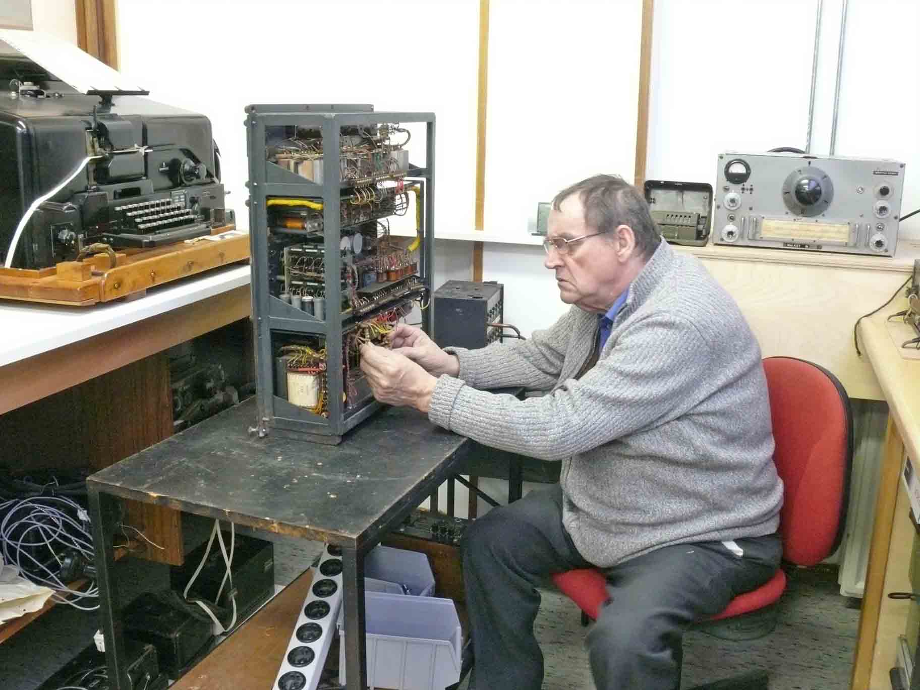
His first aim is understanding the way the particular wires are being numbered

The power section being pulled out of the main chassis, as to get better access to its circuitry and components. It can be independently operated and tested
On 6/8 February 2013
With the help of Jaap Keijzer we have been able to move the very heavy Siemens G-Schreiber type T52d onto a solid moveable table, which allows us to access the device from different corners.
From experience I knew, that accessing the gearbox is only possible when the Code-wheels-section is being tilted rearwards.

I knew from previous experience, that one should approach it with great precaution
The top-lid of the gearbox have been taken off in the meantime. In the far rear we see the top-cover taken off already.

The arrows are pointing onto the friction-clutches
Just facing towards you is the transmitter section (Sender); opposite we see the 5 bit receiver section (Empfänger). The friction clutches are normally kept being blocked, only after a starting-pulse is provided the clutches will be allowed to make a single rotation, waiting for a next pulse to come. The clutches consist of felt-rings dipped lavishly into oil
Please view also the two YouTube films 47 and 48
I have to read carefully first the according T 36Si manual. The civil type equals the centre machine section. There exists also a T36Lo type, both being tape printers, but the latter machine is completely different mechanically. Why I don't know, though the T36Si is never found in contrast to the Lorenz T36Lo machines.
The encoder is a smart device. The encoder disks are being installed in a way that it rotates as long as there is not found a closed circuit. When this is found, a charged condenser being discharged by means of the printer-hammer-coil loading. This hammer knocks the running paper strip upwards and the character being printed. The rotating type-wheel is then just printing a single character. Theoretically there exist more close-circuit positions though, the capacitor is not yet being recharged again.

The black Bakelite boxes in the rear are containing polarity-relays, which is being used as to connect and disconnect the 5 storage-capacitors, which do store the data content of the 5-bit Baudot-code. These 5 electrically charged condensers are then later being un-charged by the hammer system after all 5 signal bits have been stored
Please notice the schematic T 52D schematic
M.Dv. 35 Manual

The two glass bulbs constitute current limiters. Maybe when something goes wrong in the + 60 V and/or the - 60 V power sections. I guess, that SL 1 stood for Sicherungslampe or Sicherungsleuchte. The Dutch PTT called them BL 1 likely standing for Beveilichtingslamp, actually expressing the same purpose
On 12/13/14/15 February 2013
We have photographed so many occasions, that I would like to introduce YouTube films straight from this webpage. Creating a kind of lively photographs including sound
Film 50: Viewing inside the G-Schreiber T 52d gear box. The pressure at the friction clutches being released as to allow fresh oil penetrating deeply into the felt rings. For my own convenience, I used tools that were just at hand, the only matter that counts, is to saturate the felt-rings with oil. (00002)
Film 51: A closer look at the worm-wheel and the encoder friction clutch. It is good visible, that the fibre worm-wheel-teeth are passing an oil-bath which covers the bottom section of the gear box. (00003)
Film 52: A 'blow-up' view of the previous situation. The oil kept in between the fibre worm-wheel is good visible. You also have a good view upon the two felt rings separated by a central metal disk. (00004)
Film 53: The gear box being built together again. On top of it the centrifugal speed regulator, an essential part of any mechanical telex machine. Its perimeter (the white strips) is divided such, that using a 125 Hz tuning-fork has for 50 Baud to be brought virtually to a stand still (frosen); using regular daylight. (00006)
Film 54: Dick has repaired the cut-off wires and luckily the interface works instantly again, although the G-Schreiber interface is still causing some problems likely owing too relays-contact-oxide, however, the G-Schreiber* transmitter output is internal fed back to the T52d receiver input, so that one can read what actually is being transmitted. Single current machines, where both TX and RX are being operated in series do this automatically. (00007) * Incorrectly first written Nachtfee, I apologise for this mistake!
Film 55: The Geheimschreiber starts running again! Dick is currently cleaning a paper transport drum, which's lubrication has become too sticky. After cleaning with alcohol and re-oiling it again it runs smoothly. (00032)
Film 56: WOW, the T-52d machine starts operating again, albeit in normal telex mode only. Dick is operating the keyboard and the text is being printed at the paper tape. Please bear in mind, that in those days 'secret telex machines' world wide, were all paper-tape machines! You may ask yourself why? Can't you imagine a valid reason? The solution is rather simple, because a type writer needs when it reaches the end of the paper sheet a so-called 'carry-return' signal, in telex technique this represents a particular designated Baudot-code; though, secret typewriters convert one character into another. Hence, the 'carry-return' signal will be converted into any other character but never a carry return code; whereas a regular character may be converted into a carry-return signal instead! Most tape-telex machines have a character-number-counter, where, for example, a red lamp glows when 80 characters including spaces have been passed. Resetting the lamp is automatically providing a carry-return signal. In this case a tape-telex can communicate in cojunction with regular paper-sheet machines. (00031)
On 19/20/22/25 February 2013
A few days ago I encountered a drawback owing to the fact that the G-Schreiber interface refused any longer to link the outgoing and printing section of the machine. The Siemens Telex machines of those days were four wire dual-current systems (similarly to what I understood was also doing Creed). This means, that incoming and outgoing signal act independently. It is even possible, to receive a message and send another one simultaneously. As to allow checking what you actually are transmitting (sending) in most interfaces a special provision is build-in, by means of simply bridging a pair of contacts the machine prints what you just are typing in.
I have tried several things first, and decided to reconstruct the setup which worked well some twenty two years ago. In those days I used a civilian Siemens interface (Wandgerät ≈ 1939, also known as Fernschaltgerät) together with a Fernschreibanschlußgerät (between them 4 wires are employed). As second telex machine I use a Siemens T68, a wonderful machine, by the way! When we moved to the new museum premises in the course of 2008, I have cut the cables in a particular way, allowing me to reconnect it easily as it previously was before. It worked instantly again. Now it is possible to send and receive messages in either direction. A magic sound listening to both machines.

The G-Schreiber is setup together with the old civilian Siemens telex interface (black box - Fernschaltgerät), which is visible just right of the Geheimschreiber. The typical 13 pin Siemens connector being plugged-in

Viewing the turned around G-Schreiber and regular 'Fernschreibanschlußgerät' in the background, adjacent to it the Siemens T68 machine

Viewing the counter side of the reconstructed system being the regular Fernschreibanschlußgerät and adjacent the T68 machine. When you look closely it is possible to notice that the T68 is just waiting in space setting (negative current = blue sector)

As to understand better the nature of Baudot signals (characters), please notice this interesting table, which is valid for dual-current systems
The next move has to be investigating the original G-Schreiber interface in detail. The previous photo just showing a test, where the Geheimschreiber is connected onto the original G-Schreiber-Anschlußgerät on the right-hand side.
For it Dick Zijlmans has to remove the centre unit and we should check fist all capacitors, which might be the reason why the interface strikes (or - is it an act of deliberate sabotage again?). It is always a good feeling to have a closed loop functioning, so that sections only partially have to be repaired or interchanged. Working within a complicated system, where it is unknown how many failing chains are blocking its proper operation is often discouraging.

Dick is currently measuring whether some of the three block-capacitors is defect; which not proved being the case
He checked for electrical leakage and correctness of their capacitance, which is showing no deviation.

Continuing the test, where the Fernschreibanschlußgerät on the left-hand side being interconnected by means of four wires onto the G-Schreiber interface under test. It proved, however, that although the T52d machine gets signal, that it is impossible to get it responding on in- and outgoing signals
We should investigate this interface more thoroughly!
Please view the following video films which provide more lively information
Film 62: Dick is disconnecting the connections between the power supply module and the centre interface unit. (00038)
Film 63: Dick is operating the Siemens G-Schreiber which is being interconnected as we operated it about 1990-92 (00039)
Film 64: Viewing at the same time the receiving T68 machine which gets the text being send by the Siemens G-Schreiber T52d. Please notice the 'red lamp' indicating that a 'carry-return' is over due! (00040)
Film 65: Viewing in Dick's rear side the receiving Fernschreibanschlußgerät, viewing on the meter also the fluctuating line current. (00041)
Film 66: Video camera zoomed at the meter indicating the single current flowing between the Fernschreibanschlußgerät and the Siemens T68 telex machine. Dick is operating the T52d machine which communicates in 4-wire-mode and the fernschreibanschlußgerät convert the signal into a single current mode. (00042)
Film 67: Dick
is cleaning currently the so-called 'Flachanker-Relais' (should
be called Rundanker-Relais) contacts. Which later
proved that most of the relay bobbins being defect. (00043)
Film 68: Shown is the way the Fernschreib-Relais or Polarity-relay can be adjusted; using an original Siemens test set. The T and Z contacts being just brought in its mechanical and electrical centre. (00046)
Film 69: Test setup, where the T68 with attached Fernschreibanschlußgerät (interface) is being linked in a '4-wire-mode'. This instead of the civil interface version (Fernschaltgerät). Result completely a failure. Only the G-Schreiber can sometimes printing-out what it just is transmitting; though all in- and outgoing connections are dead! (00048)
Film 70: Apparently the windings of the bobbin (coil) of relay 'N' is somewhere interrupted. Sad, because it should have about 15 kohm resistance. This would mean that the Cu windings are using very thin wire! Relay 'N' is being activated just when the system + 60 V and - 60 V are both available. (00051)
The most problematic failing relay is designated 'U' can you imagine that? ...

The relay bobbin consist of: having 1260 ohm 13900 windings of 0.1 mm Cu in series with a wound resistor wire of 3740 ohm and 1100 turns of 0.1 resistor wire and a 2000 ohm bifilar wound resistor wire of 0.08 mm in series?? (Wdss may stand for Widerstandsdraht type 's'?)
The only reason for integrating a bifilar wound resistor inside the (coil) bobbin I can think of is a kind of temperature compensation or that like; as its nature does have a magnetic field component!
On 22 February I have tested the remaining relay bobbins and have found that currently relays N - U - P are defect. Curious is, that relay L is having two windings one regular inductive coil having a resistance of 6 kΩ and a non inductive resistance winding of 6 kΩ as well. As this may be regarded being non inductive, it probably is being wound bifilar, it may be replaced by a regular resistor. Why the resistor winding is an integral part of the bobbin I don't know. It might even be, that I have made a mistake and that the resistor section is OK and the inductance winding is open. When this is the case, also relay 'L' has to be rewound.
Please consider also the new special page which is dedicated to the: Geheimschreiber Fernschreibanschlußgerät G manual D.(Luft) T.9103

I just received an old Dutch PTT information sheet (1939) on what they called Relay type 60, though, apparently was a Siemens & Halske relay. This relay type is being dealt with in our troubles giving Telex interface
Please click on it as to open the entire relay doc
On 26/28 February 2013
Dick continued today with removing the rest of the defect interface relays (all together 4)

The bobbin (coil) of relay 'P'
It is evident that 'acid like oxidation' might have been the reason for its failure. Viewing, however, the coils windings data something is strange; a regular coil wingding having 430 Ω with 5760 turns (Cu) in series with a wound resistor-wire having 570 Ω with 240 turns. My guess, this is done as to provide the standard 1 kΩ for the bell relay circuit (Wecker), though lowering its A/W value a bit. Or, it was done as to lower its inductance a bit?
On 2 March 2013
Two new YouTube films being made
Film 77: Viewing our two Fernschreibanschlußgeräte. I have inserted an original telex single current connector into the regular FAG apparatus, which is an improvement, as from now on the switch: call or disconnect (Schluß) is fully operational. On the right-hand side we see our second FAG. This set was made by Lorenz, and was likely adapted in post war days by the Germans when it got more modern Siemens Telex relays. It is not yet working appropriately, though, it should do so soon again. (00057)
Film 78: Viewing the right-hand side compartment of the FAG-G interface, where three of the defect relays were fitted, which have been removed. (00059)
Film 79: Shown is the left-hand side relay compartment of the FAG -G interface, where the quite complex relay designated 'L' is mounted and which has been removed for its rewinding (repair). (00060)
On 18 March 2013
I continued with investigating the reason why the motor inside the coding section refuses to operate. The complicated cable wiring of the Geheimschreiber T52d is rather confusing. A wire fed onto a particular connector having a wire number is disappearing somewhere onto. When you might have traced it, what is to be found is adding even more confusion.

What to think of this wiring plan, and finding out what the implication of a certain wire is?

My first aim was to be for 100% certain that the fault is being caused outside the coding module, I tested whether the 220 V is provided at the appropriate contacts. I was tricked by the curiosity of the wiring, as cable number 272 was carrying 220 V, but is was apparently discovered that this wire was only being operated when the system was running on a dc mains voltage. The two glass bulbs belong to the + and - 60 V current-limiting (protection)
After having investigated where it might go wrong, I decided to demount the entire coding chassis. Demounting on its own rights is not very difficult, but it is actually just a bit too heavy for a single person to handle.
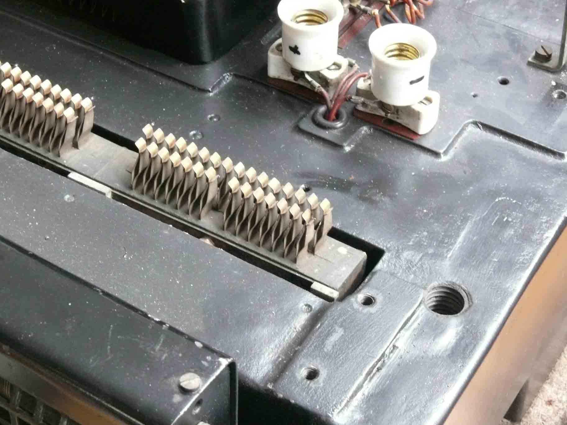
The entire coding section being removed. The most 4 right-hand side contacts are related to the 220 V motor supply

However, replacing it without damaging the delicate contacts is another matter. Particularly when no one is around to assist!
The electrician-pliers is to function that during the remounting of the coding-section that contacts will not be damaged owing to the fact the knife-contacts not yet centred can be destroyed.
However, I managed to do the job without problems.
During my tests I discovered that the FAG versus the T52d interface acted not as usually. Why?
My thought soon was, is somewhere +60 or - 60 V lacking?
This was actually the case within the Fernschreibanschlußgerät (FAG)

Luckily it is provided a test selector and it was quickly found that - 60 V was missing

My first thought, do we have to deal with a faulty fuse?
Yes, we have.

Please notice the text below, explaining why this fuse type was once in Germany quite commonly used
Why, because the Germans used for delicate low currents purposes special 20 mm fuses, though, having a least at a single side a tapered diameter. It is by this means impossible to bridge a light faulty fuse by a too heavy sample! However, these are no longer on supply. My trick is soldering at one end a small M 2.5 screw-thread of, say, 2 mm length. This method is simple. But, when the fuse is having a too low value, think of 100 mA, than it is becoming a delicate job, as most fuses are having a spring-loaded wire, which responds mostly quicker than the screw-head is being fixed. Sometimes it works when you are lucky.
I also made a new series of YouTube films
Film 80: Viewing the irregular motion of the code-wheels when I operate the keyboard of the Siemens T52d Geheimschreiber, a German top secret telex machine of 1944 (00062)
Film 81: Viewing Siemens Geheimschreiber T52d code-wheel motions from a different perspective (00063)
Film 82: The code-wheel step mechanism, this only started to operate since today, after clearing difficulties encountered (00064)
Film 83: I apparently have forgotten that about 23 years ago the motor-connections had been disconnected. Hampering was, that these electrical connections cannot be noticed without dismantling a part of the code-wheel system (00065)
Film 84: Viewing the code-section motor and its contacts, explaining some guessed reasons why the electrical motor stroke firstly (00066)
Film 85: We are viewing the moving code-wheel-rotors from the rear side of the Siemens & Halske T52d Geheimschreiber machine (top secret telex of 1944). Please do not be confused thinking of the Lorenz SZ40/42 machine, which codes were broken at Bletchley Park (00067) A few days ago
Please view also in section 7 the two additional YouTube Films
On 20 March 2013
A few days ago it was found that the electrical coding-system-motor should need attention and its bearings are to be lubricated. Including other bearing-gears.

For it the motor had to be removed, which could be accomplished quite easily

Viewing the gear-mechanism of the code-wheel stepping system (view please also the next two YouTube films
Film 86: Viewing the reinstalled re-lubricated electrical motor. It is responding soundly when the telex is being started and the coding-mechanism is responding (00069)
Film 87: Viewing the code-wheel stepping mechanism in action (00071)
On 28 March 2013
I have accessed the Geheimschreiber again, this time aiming at an experimental method by which means it is possible to measure the electrical circuit wiring of the 5 bits Baudot code system, which is to be received by what is designated 'Empfänger'. Testing its 5-finger-switching-arrangement for its conducting resistance between the switching contacts and the 5 polarity relays. Secondly, measuring the quality of the 5 data-storing capacitors. For each of the 5 data-bits individually.
My first thought a few days ago was, to access the rather complex selector switch for 'Klar - Geheim' (open - or secret text) from below the T52d chassis. This sounds easy, but it is not! Please bear in mind, that the Geheimschreiber machine weights about 80 kg, not simple to turn it upside down. On its side is an option, but owing to its dimensions special prophylactic precautions should be considered! Especially the coding section is a delicate matter.
My second thought was, why not removing the 5 relays and trying to measure the resistance between the 5 bit receiver contacts and the feeding points of the (removed) relays?
Our Fluke multi-meter could not cope with the circumstances; whether being caused by the capacitance of the data-storage Cs or residues of some of its electrical charge I cannot judge. Therefore I took the old Philips analogue meter which full scale is up to 10 Ω. This apparatus works for measuring low resistances far more convenient than does the Fluke hand-held digital meter!

One test cable being inserted in the feeding point of the (removed) 'bit 2' polarity relay. The white meter scale being a bit over illuminated (exposed). One side of the ohm meter cable being plugged in one plug of the eight-pin relay socket holes

The other measurement concerned checking whether the 5 storage capacitors are having the correct capacitance combined with a low loss (tg d). The RLC bridge being brought in balance at about 1 µF (1.1 µF)
I measured between chassis and the 5 receiver output contacts. All 5 Cs were still in a good shape! The Germans were specialists in making such excellent capacitors. These are of the so-called: hermetically sealed off type, doubtless expensive, though, lasting now for 70 years! It has to be noticed, nevertheless, that for mass products their standards deteriorated after say, mid 1943, as the war should not last for 70 years to come! However, T52 machines were definitely very expensive apparatus and were still fit with quality products.

I made notes as these contain valuable detailed information, which some days may be very helpful
The upper row constitute the Baudot-code bit numbers
Followed by the data signal input contacts. All at their inputs being fed by the same signal potential
The next line representing the individual data-bit sequence
The Rel 1 - 5 are connected galvanic onto the data output switches (F 19 .. F 18 ...
In between it (F 19 towards Rel 1 ..) the cabling is being fed onto the selector Klar - Geheim (open- or secret text message). Operating the 'Klar' mode direct connection should exist.
Also helpful is it as a reminder to the numbering of the data-bit relays. After a while one might doubt whether Relay 1 - 5 is counting from the front side up or downwards.
On 31 March - 5 April 2013
I continued with discovering the functions of the various relays involved; still some functions or interactions are not understood yet.

For it studying schematics is crucial. The original available T52d schematics are either vague or showing not all details necessary
It proves to be very helpful to use for many functions the civil schematic of the Siemens T36Si machine. Both apparatus are rare and very difficult to find. The civil Siemens schematics are very clear in combining functions and its electrical interactions.
Please notice the next schematic, which is the cleaned-up version. Not a particular difficult job though, definitely a time consuming one.

The civil schematic is very handsome, as it is very clearly explaining how the electrical telex machine works. Both types SFM T52d and T36Si are operating the same telex unit (combined receive - transmit and printing system). Even the cable- and part numbers are identical. The secret telex section is at will selectable and is implemented between the receiver (Empfänger) output contacts F19 - F25 and the ingoing connections of the polarity relays-coils R1 - R5; which bi-stable positions + or - switching contacts (equals T = mark and Z = space) are then both connected onto the encoder or Übersetzer section
As to download in in A2 format, please click on the above drawing

Heinz Blumberg very kindly provided an A2 size like T52d schematic. However, of a completely different nature although, seemingly it has much in common with the previous schematic; maybe not directly recognisable
As to view it in A2 format please click at the above drawing
I continued first with finding out some of the relay functions (which relay is doing what)

A curious relay of which I firstly thought that it was relay designated AR, as its snubber arrangement equals the one shown on the schematic. This proved after measurements and other considerations being a mistake! Please notice, for instance, on the right-hand side the 'K' numbering
After comprehensively studying the schematics, it is found that it is having a function in combination with the KTF on - off mode selector; which is just visible on the right hand-side.

Viewing the above relay from a different perspective. The word 'KTF' is just visible on the right-hand side

The text task is deducing the numbering of the various switching contacts; as these are becoming rather vague or even unreadable (70 years old!), and it is found that it does make sense recording it in a notebook. It can also be found in the T36Si manual, thought who possesses such a handbook? We luckily do
On 4 April 2013
With the kind support of Jaap Keijzer I was able to tilt the Geheimschreiber machine backwards and we mounted it such that it stands stable under an angle of, say, 75 - 80 degrees. The reason, is, that the gearbox oil should be kept inside it.

For it I used two rectangular wooden bars (balks)
Please notice the cable trunks below
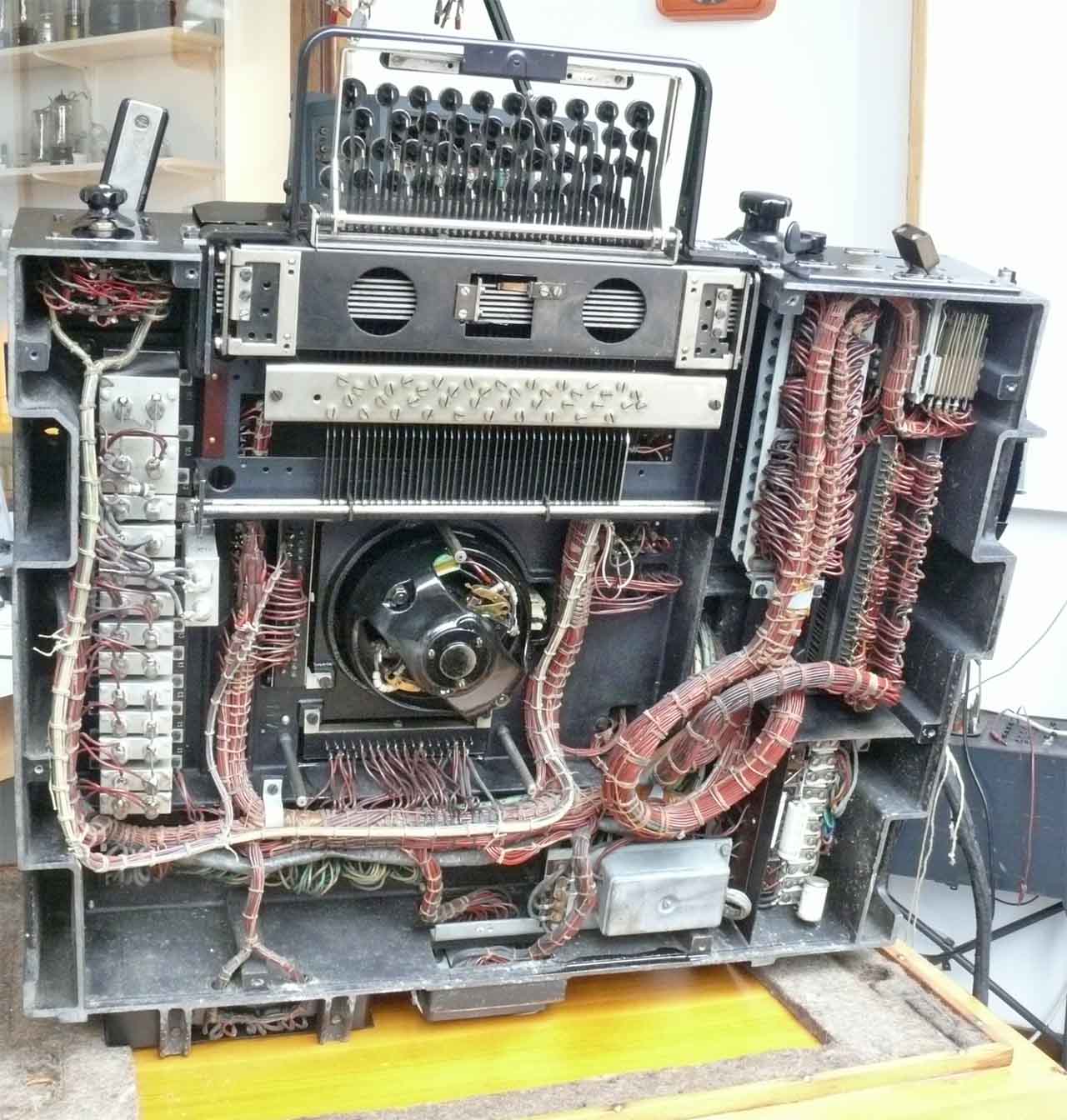
I also made a discovery, please look at the thin cable trunk at the far left-hand side
This is on one side connected onto a selector switch designated R 1 - R2 and R3, however, on its other end being connected onto the 5 bit memory relay (designated R1 - R5). Why? Is this meaning that some kind of additional interchanging of the 5 bit Baudot code is provided or: are the T = mark and Z = space contacts being interchanged at will? We have to bear in mind, that our machine has been employed by the French Navy for about a decade (my guess mid 1950s - 1960s). The way the selector is being wired is showing that they delivered an extremely poor quality fitting (craftsmanship); really a shame!
I also checked some filters and capacitors; these are all of the hermetically sealed off type, thus most likely in a good order. The only curious thing found was the dual suppressor-filter FE 3? in the - 60 volt line?, which I have bridged by a two wires temporarely as to be sure that non is causing problems. Visually it showed some signs of overheating, whether this is valid I cannot yet answer.
Digesting the last photo one doubtless can see that the Siemens Geheimschreiber T52x is an electrical machine indeed! Tracing wires is hardly possible, as these nearly all having a single (brown like) colour.
Considering the problems we currently are facing, my estimation is that our 'Geheimschreiber Repair Project' might be a long lasting undertaken! As too many aspects need thorough investigation
To be continued in due course
By Arthur O. Bauer
Please consider also: G-Schreiber repair headache
Please also consider, or proceed with: G-Schreiber various docs
![]()