
Exhibits details page 4
After some considerations we have decided to create a new additional webpage, as the forelaying Exhibits details page 3 is becoming too much overloaded.
Created on 6 November 2011
State of affairs: 12 January 2014
For your own convenience, we would like to advice you to use the search mode
for Windows users: Ctr + F
and for Mac OS X users: Cmd + F
Entre your particular search word and all those words inside this document will be successively shown
On 7 October someone very kindly gave us a Fremess a
(1)
This wave meter type is, although completely different in concept comparable with a BC221.
This set is having 20 bands (30 kHz - 30 MHz).
In contrast to the BC221 this set is not relying on harmonics but is using direct signal generation.
The main difference between this set and the pre-war K126 Rö is that the latter housing is made of die-casting and later in the war they used steel plate material
Front panel of our Fremess a

Fremes.a, Serial number 6040, year 1943
As like a BC221, this set also needs a calibration book for all its 20 ranges. But, is using a fundamental signal generator in contrast to the BC221; where for higher ranges they employed signal harmonics, with all its ambiguity nuisance.

The valves are accessible when the apparatus rest at its back, which is also the regular way it should be employed

Looking from the bottom (housing being removed)

Viewing the right hand side of the set
The die-cast chassis is well visible we also can see that the chassis and front panel is a single piece of die-casting.

It is clear that the turret arrangement is constructed soundly, and is of typical Telefunken design

It is evident, that the design of a Fremess a goes back to the mid 1930s
However, it apparently full-filled military requirements. The individual who donated this set told me when he brought it to us, that it generated even at 30 MHz a stable signal (according the manual the accuracy is 2 ‰).
On 18 October we continued with:
the Lo40K39-d extra
(4)

Lo40K39d
This version was also used (maybe only for) reserve transmitter in U-Boote (submarines). In some respect its design differs from the regular Lo40K39..
It is also clear that the power supply is housed in the upper section and that the transmitter is mounted in the lower section. I think that this was done as to minimise temperature influence of the oscillator stage. As to increasing frequency stability.

We have to apologise that the type plates are a bit difficult to read

The main difference is that in contrast to regular sets, this type is having its connectors in the rear side and not on the right hand side

The main difference in the antenna tuning section is, that some of the matching pre-settings are being kept blank, thus these are not available. The matching condition onboard U-boats is having a more or less limited matching range. In universal operations the set must be able to tune between 3 and say 14 MHz for all sorts of antennae. Be it very short or relatively long ones

The rear side of our Lo40K39d
Please notice the connector at the bottom.

The inter-wiring of our Lo40K39d

Power supply of our Lo40K39d

A rear view of the Lo40K39d power supply
Please notice the mesh-contacts, which can only be found in the /d version.

Top view of our Lo40K39d power supply
Just between the transformer and the front panel on the right hand side - we see the mains loading capacitor, which should protect from "switching-on" power failures. A transformer is having before the core is being magnetised a rather low impedance hence, is consuming a high starting up current. I my perception, more designers should have done this. Who never encountered the phenomenon of blowing-out a fuse when a system is being switched on? It often is caused by choosing a too small transformer core.
On 3 November 2011 we continued with:
The Körting version of the famous HRO receiver

KST receiver with its power-supply/loudspeaker

Like the original HRO frequency band (range) is changed by means of a coil-box

Our KST carries serial number 0306
Shown is Bereich 2 (range 2). Running from 11-22 MHz

Inside the top-lid is attached the explanations of the receiver controls

Extra informing: that the receiver is not to be connected onto the regular ground, though, only by means of the regular antenna; such as dipole or antenna counter poise

Top view inside the RX compartment
The tuning capacitor with its gear and tuning-dial was purchased from the US. Albeit imported indirectly via Portugal.

Filter-quartz at 468.0 kHz

Bottom view of the KST receiver
The black cable at the top left is interconnecting the RX and its power-supply/loudspeaker module
It is clear that some post war modification had been implemented. I obtained this set in the 1970s from Ebbe Pedersen. Whether he himself has done it I doubt.

The power connector is a substitute
Although, we have some years ago got the original one, we haven't had time to replace it

Viewing the interconnections

The two red rectifiers might have been adopted after the war, as its connection is coming from the original valve base

Viewing the bottom-side of the KST power supply
It all looks quite straight forward
On 6 November we continued with:
Morseübungsgerät
(5)

Controlling panel of the Morse trainings apparatus

Type Gl: S
Lieferer: Dr. Georg Seibt A.G.
Anforder Z. Ln 127001 (GAF stock number)
Bauart: Seibt (type after Seibt)
Hersteller: Seibt (actually manufactured by the Seibt Company)

Inside view of the Gl: S

Different perspective

The E 14 socket is meant for the neon lamp, which acts as switch-off device as to discharge a loaded capacitor at a given break-down-voltage

Schaltbild für Glimmlampensummer
I trust that with some fanatacy and knowledge of its principle, that one is able to understand the circuitry
Changing subject and regarding some items of our
Telephone related displays
(6)

10er Klappenschrank mit Wählerzusatz
10 lines field exchange unit with attached number dialing
This is a widely used device
(7)

Wählerzusatz
Attached telephone dialing module, as to act as an interface between field-telephone-systems and the regular telephone exchange system.
On 17 June 2012
A new item is brought on the web
During a meeting held in Dresden the last few days of April 2012, I saw on an exhibition an old Lorenz apparatus with an inserted quartz of 35.2 MHz. I was instantly paralised because I was already looking for it for at least two decades. Immo Hahn was so kind an gave it to me. I promissed him that he will in due course get one in return fitting more for his purpose.
(8)

35 , 20 MHz 8,528 m. Manufacturer Carl Zeiss Jena
Carl Zeiss may be regarded the only company in the work capable producing quartz for very high frequencies. This may have been made possible because it was one of the world's major optical firms. Handling these kinds of piezo-electric vibrators is 'high arts'
It was found to be a good occasion measuring its parameters

This µP controlled quartz impedance meter type 150C made by Saunders USA
Series resonance (Fs) at: 35.20578 later it moved to 35,20549.1
R1 40 Ω later moved to 38.2 Ω being the virtual quartz loss resistance, which is the only measurable parameter, because in series-resonance L and C having equal values and becoming null. The value of R1 is remaining
C1 being 0.0008974 pf (going into femto farads!)
The value of R1 is for modern days not particularly good, but regarding its high frequency and maybe the fact that it is made from tourmaline it is still is a good figure. The Germans used mainly Pierce oscillator circuitries. Which constitute in parallel mode resonating circuit. Their frequency is to some extent tuneable, in contrast to series resonance.
This quartz test set was some years ago obtained from the 'bankrupt' Saronix Quartz factory in Doetichem NL, which formerly was owned by Philips. Thanks to Donald Prins I was able to buy this test set as well as the most rare quartz measuring arrangement according IEC 400*, both importantly including all auxiliary parts to it!! Although, he had left Philips Doetichem for a while, he was the only one who knew where all the various parts were being stored. One may think of a great hall, but the manuals were stored on the first floor in a particular cupboard. No one knew this. For those who came to collect their purchases, he was their men! * Donald had to buy the rather big test table completely as well. Luckily this was foreseen by some who took over, of course gratis, the remains! Alone this table being > 2 meters broad and I guess >1.5 m high. He was so kind representing me during the auction as well as gathering the purchased items, because I stayed in London.
You may be interested in what application this quartz was used. It was utilised in a Blind Landing test set type PSUo-A (PSUo-B). Maybe a good occasion to photograph this set in details in due course.
On 20 June 2012
As promised: the PSU-O-B
(9)

P.S.U. o.B. Prüfsender U o.B
Bauart: Lorenz
Gerät-Nr. 124-1403 A actually a drawing number
Werk-Nr. 95318 serial number, likely scrambled
Anforderz. Ln 27146 (GAF Stocknumber
Hersteller: Philips - Berlin
No doubt Philips, likely Eindhoven. Philips Berlin was only a trading company
BAL is the acceptance stamp
BAL = Bauaufsicht Luftwaffe; 299 is the controllers identification number. He was responsible for the correct acceptance (Abnahme)

Front panel of P.S.U o.B (o-B)
Its purpose was for checking the Lorenz Blind Landing System. VEZ means Vor Einflugzeichen (pre or first landing beacon signal); HEZ means Haupteinflugzeichen (the second or main landing beacon). Test was done at: 30.0 MHz - 30.5 - 31.0 - 33.33 and 38.0 MHz.

P.S.U 0-B viewed from the front panel
The left-hand section contains the tone coils which were used for the two landing beacon recognition tone signals. Where the third one is used for I have not yet determined. The 35.20 MHz quartz crystal is fit on the rear of the right-hand side. One may wonder why 35.20 MHz? The reason is simple, signal processing is done by means of a super-heterodyne principle, where the quartz is being mixed with a rather low settable frequency, as to improve frequency stability. Likewise was done by the various landing beacon transmitters. Please view also: D.(Luft) T.4052: Einstellsender PSUo-A, Betriebsvorschrift manual.

Upper left-hand side, the typical Lorenz type tone frequency coils are clearly visible. These are also tuneable. In the background the service mode switch: Betrieb - Eichen (operate - Calibrate) The valve is type RE134, well known in those days

Viewed now from the far left. That Philips was involved is considering the components well visible. Such as the typical tar transformers and sealed-off capacitors. The small lamp may indicate that a bridge type oscillator is involved

Viewing from the rear side. On the lar left the 35,02 MHz quartz together with its oscillator valve type REN 904. A well known oscillator valve used in my transmitters. For the four bridging links please notice: D.(Luft) T.4052: Einstellsender PSUo-A, Betriebsvorschrift

The channel tuning on the right-hand side. Please notice the typical Philips ceramic capacitors and the copied Siemens & Halske like Sikatrop hermetically sealed off types. My guess, the trimmers were made by Hescho

The left-hand channel tuning section. Both valves type REN 904, on the far right just visible a RE 134

Over view of the various channel settings
A new device is NAPH
Netzanschlußgerät Peiler Heinrich
(10)
The power supply to Peiler Heinrich The VHF DFing equipment. Associated to the Y-System (Ypsilon-Verfahren) like was Teerose in the Netherlands as well

NAPH serial number 3515, this may well being a scrambled number; ded is the manufacturer 'ded'

ded stood for: Heliowatt Werke, Elektriziäts-Aktiengesellschaft, Werk Schweidnitz/Schlesien

Front section of NAPH
This power supply is a quite heavy device

Cover taken off. Please notice the 'EP' on the left-hand side: Empfänger Peil (DF receiver). Fu may have meant Funk, whether a transmitter was dealt with?

NAPH inside, viewed from the front left side

NAPH inside viewed from the front right
A new item is the rotary convertor or Umformer U.0
(12)

Umformer U.0
Providing 220 V ac derived from the 24 V aircraft battery. It was used for all sorts of things, like letting the P.S.U.o.A or B operate from the 24 V aircraft battery. It delivers at least 50 W.

Umformer U.0.
Bauart: C. Lorenz A.G. Berlin-Tempelhof
Gerät-Nr. 124-304 A (drawing number)
Werk-Nr. 95374 (scrambled serial number)
Anforderz. Ln 27157 (GAF stock number)
Hersteller Philips - Berlin
Philips - Berlin was only a trading bureau and it may well have been manufactured in Eindhoven

Its 24 V power cord is wound up on the top

The U.0. DC to AC convertor (24 V dc → 220 V ac)

Viewing the 220 V ac output side

Viewing the input side control. The On - off switch combined with the adjustable output voltage setting (220 V ac)
On 25 April 2012
A new interesting artefact is contributed
I obtained this artefact in the 1970s from Ebbe Pedersen, always having in mind that it is worth keeping it and showing it to the public, in due course. Although, no one would have known what the tremendous impact the Internet would get. Even the word 'Internet' did not publically exist!
(13)

The solid ceramic VFO housing of the U-boat transmitter type S 406S/36
Every time when I look at this device I am impressed again by its solidity. The copper/ceramic housing is even soldered upon! Submarines, but other ships as well, may have sometimes to cope with very strong resonances. Mr. Karger told me once, that he was a test engineer at Sauter in Basel, and that they had to build measuring equipment for Russian cooling ships. When they were in the testing face, they encountered enormous problems. Components were simply ejected out their printed boards and shock mountings were taken apart. Paper rolls were starting to un-roll and more of these extremities happened.
The VFO principle is based on: Push-Pull oscillator followed by a Push-Push stage. This is a stage which has a symmetrical input and where both anodes are being connected in parallel. Such a circuit can only deliver odd harmonics ( 3, 5, ...). When necessary, one valve is being grid blocked and the other valve is acting like a normal amplifier. The being blocked one is acting as an ideal neutrodyne stage. Similarly is done in the more advanced transmitter type T200FK39

(in the T200 FK39 VFO photo, the valve most on the right-hand side; we are viewing there at a single oscillator and a single push-push stage valve)

Please notice that this schematic is belonging to the T200FK39 transmitter, but its concept is equal. In both cases relying on REN904 triode valves. Maybe a bit aged for a 1939 transmitter, this valve type is, nevertheless, well fitting to its purpose. The S406S was designed about 1936/37

Viewing underneath the two oscillator valves

Viewing at the tuning variometer. Impressive is the way its two inductance wires are deposited onto a common ceramic bar (in the centre of this photo). All critical inductances are deposited this way, also the short circuit ball (variometer) inside the ceramic cylinder as well as its counter inductance

We are looking at the REN904 valve sockets of the push-pull oscillator. The two push-push valves are mounted inside the main S406S frame, whilst these are an integral part of the T200FK39 oscillator module

To give you an impression how the screening cover plate is deposited on one side with quite heavy copper. It is clear that flexibility is hardly existing

Viewing on the right the outside of the coppered ceramic cover plate

On the left the VFO and on the right the copper deposited ceramic cover plate. Please notice the solid soldering! My guess, this is only possible when the ceramic bodies are being heated up to about the solder melting point. Consequently, this had to be commenced before other components can be fit (wired) into the frame

Side view of the S406 VFO
I hope that you like this outstanding device as I do!
For those impressed as well, you can also view our T200FK39 webpage
On 23 July 2012
A new quite rare device being displayed
(14)

The quartz box to the Radione transmitter R 20M
These quartz crystals differ from the regular German quartz, as they are having a lower profile, necessary when the R20M transmitter being operated with its 'control door' closed
To be continued in due course
Finally our:
Berlin radar considerations
This Berlin related contribution does not entirely reflect what we actually possess, but is attached as it forms a subject of which we have some parts, like the Berlin PPI display unit SG224 and the pulse forming network LK1 (Laufzeitkette) and the pulse step up transformer.
After I presented my paper to the CAVMAG 2010 conference held on 19-20 April 2010 (The German Wartime Struggle to catch up with Allied Power Magnetron Technology), I discussed with Hans Jucker the properties of the pulse-forming-network type LK1. Which actually must have been a copy more or less of the same circuit found in the remains of the Rotterdam apparatus (H2S early version). He soon calculated the electrical energy stored in it. Its title is: Modulator of the German Berlin microwave radarset (equals GAF type: FuG224 or Berlin type A). I obtained these parts about 1980 from late Ebbe Peedersen of Denmark. Putting all facts together, I guess, that it remained from dismantling of a FuMO81 radar set which was captured by Danish authorities in 1945. Whether with or without British approval, I don't know. I obtained these components as it fitted to my future strategy. Although, I myself never could have foreseen that it ever was possible to swop the very rare Berlin radar PPI display unit (SG224). And showing it this way!
We very much would appreciate to find other Berlin radar modules or pieces

Pulse forming network type LK1
Please see for its circuitry Hans Jucker's paper
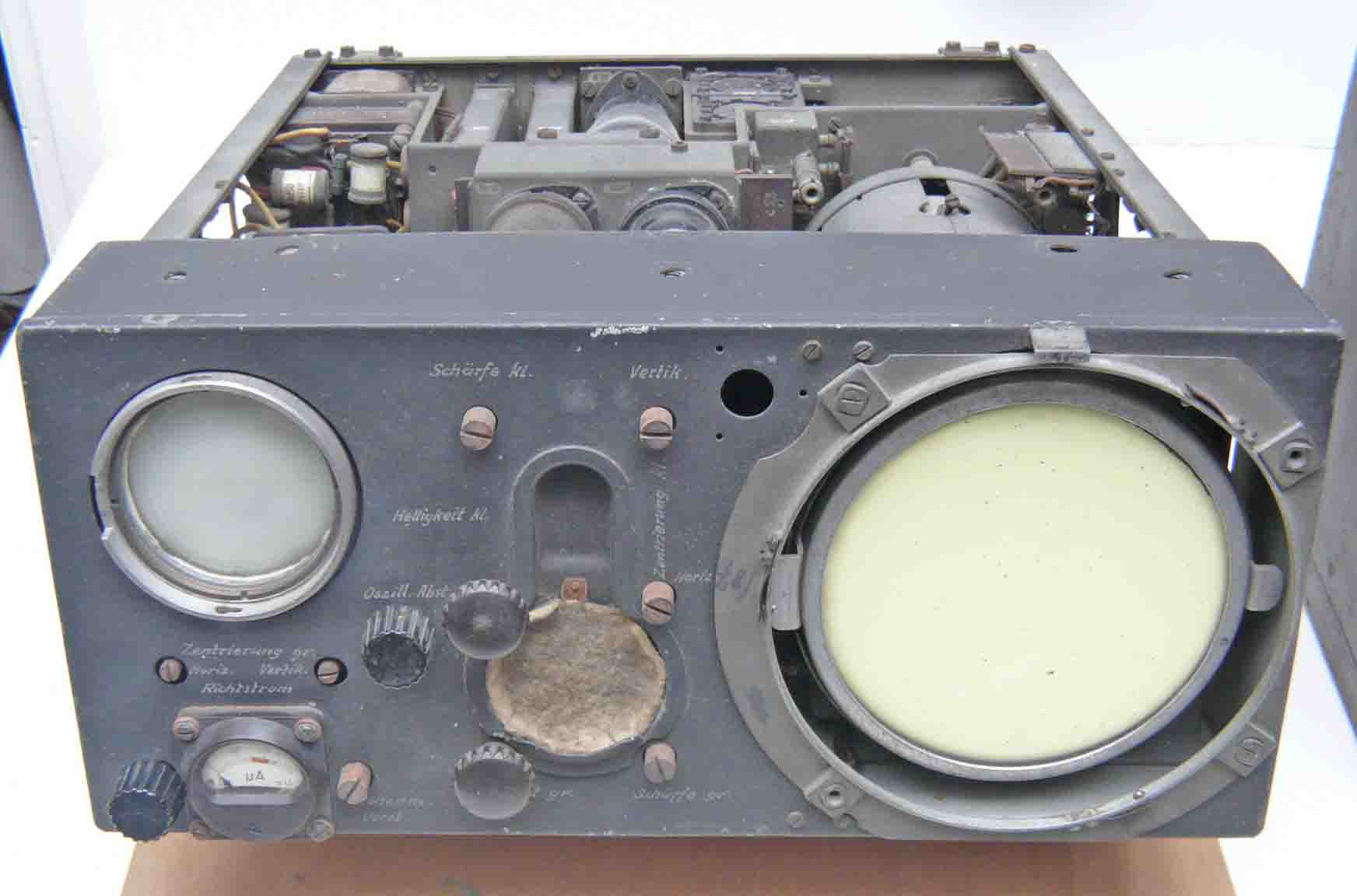
Berlin PPI display module type SG224
This module was obtained from Britain, some years ago
The following Berlin radar related photos, is not part of our collection, though being meant as to show how some modules look like

Berlin A type transmitter/receiver front-end

Feld II of the Berlin A system (serial number 391)
The upper module is like the previous photo, the lower section contains the modulator. In contrast to British H2S, it does not have the pulse forming HT section integrated as this was by German redesign an integral part of the transmitter section, which is from a technical point more appropriate, as the 10 kV pulse signal does not have to be fed by means of an external HT cable.
Feld I

Feld I (module 1)
The timing (waveform generator) section including the IF stage. This module is the top one left on the last photo

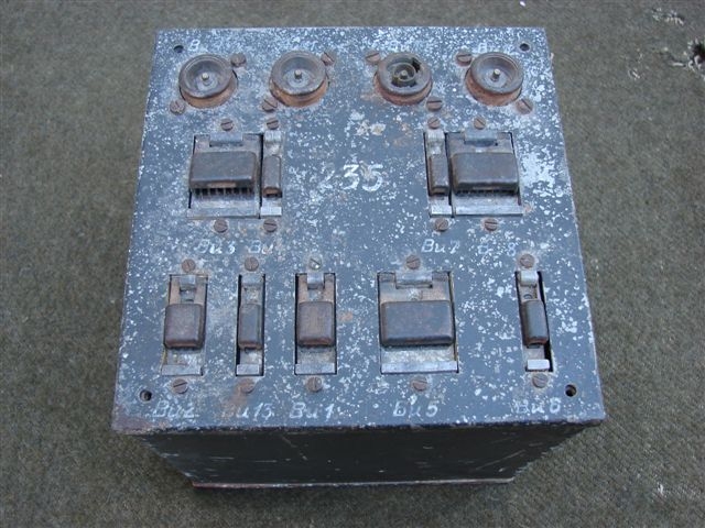
VK224
Control box of the Berlin radar system, its main function is to interconnect the system wiring incorporated in a single unit
Some time ago Horst Beck did send me the next photo
VK224, apparently the Naval version, Thus representing the same function as the previous module
This device was offered to Horst Beck some years ago though, he has rejected it (maybe too expensive?)

Berlin radar, mounted at a frame. Most likely of navy type (FuMO81 = FuG224) This type of mounting often was called: Prüftafel (Testing rack). I guess, it would have had then designation PT 224
Although, the text on top of the mains switching box indicates 230 V 50 Hz, this might have only controlled the voltage convertors for 80 V 500 Hz, like was used for H2S as well. Curious is, that the Germans, like in most other continental countries used 220 V 50Hz. Probably tailored here for British circumstances.
We would be very pleased to get any kind of feedback from those who have or can add additional information.
Please notice our e-mail address up this page
![]()
Please type in what you read
Arthur O. Bauer
Please notice also our: Exhibits details page 1
Please continue with, or return to Exhibits details page 2
Please continue, or proceed with: Exhibits details page 3
Please consider also: Exhibits details 4
Please consider also: Exhibits details 5
Please consider also our new Würzburg repairing survey: Wurzburg report
Concider also, or go back to: Archive displays
Consider also, or proceed with: Exhibits registration
Back to: Exhibits new
![]()