
Klooster exhibition (new)
Studiensammlung
in progress
State of affairs: 24 May 2013
Shown is a part of our new exhibition venue
For your own convenience, we would like to advice you to use the search mode
for Windows users: Ctr + F
and for Mac OS X users: Cmd + F
Entre your particular search word and all those words inside this document will be successively shown
For some detailed subject photographs please click on this link (in progress)!! (Please notice the recently added information on Berlin-A type radar FuG224 = FuMO81)
Please be aware that due to over loading the previously mentioned webpage, that a new webpage has been created, which is extending the exixting Exhibits details page 1. However, for the most recent information you are adviced to afterwards continue with Exhibits details page 2
Please notice also the (new) progress of our attempts: Bringing our Würzburg FuSE62D apparatus in working order again. Its antenna output is, of course, not radiated but being absorbed fully in a dummy-load. Until recently this is done by means of a Heathkit dummy-load, though, it is now commenced by the original power meter type: Ln20978. A major consideration is: that when we would encounter essential problems, which would have forced us to change components we would certainly have postponed this intriguing project! (in progress)
The entrance hall of our new Exhibition place
The set displayed on the left is Lo70KL40, a very nice long- and shortwave transceiver, with 70 watts antenna power. The parts stored beneath it, are spare parts belonging to the transmitter type G1,2K (KWSb 1,5), standing just opposite

Lo70KL40 (also known as Marine Heinrich) seen now from the opposite side. The blue/grey unit on the right is the power supply. In the centre is the antenna tuner, which is internally being interconnected onto the receiver and transmitter

This panel shows, from top to the bottom, FuG25a (Erstling) IFF transponder designed and made by Gema, with control box and automatic fuse/switch (Selbstschalter), the module (in broad face) is the shore based receiver Gemse. Its video-output is connected (correlated) onto the range presentation CRT of Freya- or, in some cases, also to Würzburg radar. On top of it stands the aerial (rod)with attached antenna-matching-box. The unit below concerns a, what the Dutch call, "Mariphone", a VHF naval radio/telephone type Lo10UK39 (also known as Marine Fritz). It is based on a Lorenz aircraft radio/transmitter design, type FuG16/17. For naval deployment, it was redesigned and, for instance, the valve filament voltage was changed from 24 to 12 volt operation
Left of the display above, we encounter next:

PT10 (Prüftafel 10), right of it PeilG6, together it represents FuG10P
Click for the manual of PeilG6 on: APZ6
In the front is shown the "Funkertisch" of the aeroplane type "Bücker Kurier" (I was told recently, that it concerned a: Siebel Si 204). The main instrument is called "Funkpeiltochter". Which has a double function; the centre instrument is a slave compass (Tochterkompass). The outer ring is synchronized electrically with the DF loop, via the compensating Funkbeschicker type FB11 (open on the right). On the left hand side is shown PT10 (Prüftafel), which represents (is equal to) the FuG10 aircraft systems. The opened instrument on the far right is the Funkbeschicker (mechanically linked) to the rotating DF loop of EZ6 (PeilG6). Its main function is, to compensate the distortion caused by the shape of aircraft owing to the asymmetry between wings and fuselage. For this occasion the table has been pulled-out towards us.

PeilG6 (PeilG VI) with receiver EZ6 - V6 - RSS6 - EPR6 and perspex (plexiglas) sense-antenna disk
The open FB11 (Patin) shows on its outer circle the trough bearing of the iron powder DF loop. The Al. curved disk is to compensate the specific distortion caused by the asymmetry between wings and fuselage of an aircraft. For this occasion the covering dome is removed and is visible right of the frame. Click for the electrical circuitry of the Patin FB11 link (the drawing quality is quite meagre but it is the best we have) This schematic belonged originally to the Patin system V25 but was rarely being used. Most systems were EZ6 + V6

PT10 and PeilG6. The "Funkertisch" is now pushed back in its regular display position

FuBL I (Funkblindeanlage I)
This transport case contains an EBL1 and EBL2 (blind landing system), interesting is, that it has a repair label indicating that it was sent for repair from Riga to the GAF repair-service in Berlin-Teltow, in 1942. This case later turned-up in post-war Spain. Left to it a "Libellenoktant" employed for night navigation in aircraft. The two yellow devices are both so-called Notsender 2 and 4 (emergency transmitters)

Shown is our Army section (Heeres equipment)
On the upper shelf we see Torn. Fu. d2 - Torn. Fu. b1 - 15 WSEb
Down of it, similar sets, but now opened and viewed from the rear, so that one can look what is inside. On this shelf on the far left, we see Mienensuchgerät Wien 41 (Mine detector type Wien 41). On the right, we see: UKWE e - 10WS h - Funksprech f with its loudspeaker. On top of UKWE e is MWEc

Torn Fu and Feld Fu corner. On top left, the tall set is Ton Fu.g On the right hand is shown our "Rariteitencabinet" this Dutch word may be translated in "curiosity display". All sorts of curious bits and devices

The upper shelf displays Torn Fu x and Feldfunk x sets (kind of Walky-Talkies)(Feldfunkgerät type b - c - f) ,. The second shelf from left to right: AE1020 which equals to some extent Torn.E.b and right in the middle section mine detector type Wien41 (Mienensuchgerät Wien 41). having, however, 2.4 volt valves type RV2.4P700 instead of RV2P800s, and its frequency range is extended to about 15 MHz instead of 7050 kHz. TornE b; Feldfernschreiber. The motor-generator GG400 (sand like colour) is to charge 12 volt batteries

Navy corner
Most devices are related to Navy Communications. On the right we see Lo6L36 and Lo6K39, - EO509 - Ulm E53b - Köln E52a1 - transmitter AS59 - T9K39 Main receiver - transmitter S406/S 36 - Ha5K39b - Lo1UK35 - Ha15K42 and on the far left a Feldfernschreiber

From left to right: Funkhorch (FuHE. ...) type: b - c - d - e - f and u. On the far left, on top of the mast, is mounted the broad-band-antenna to FuHE f (version of 1944, as previous systems used motor-controlled "Reusen-Antennen")

In the background we see our Würzburg installation (FuSE62D - FuG 62D). From right to left: Rehbock FuZG64 - puls modulator IG62a (Igel) - IF module ZFV62 (Zobel) - on top of both SÜ62d Urechse - EAG 62 (Emil), fine range measuring display - ANG62 (Orion) overall range and beam observation displays - Power meter to FuG62 and type 65 (Giant = Riese) as well as Mainz FuSE63 and FuSE64 - valve tester to Würzburg and Mannheim apparatus Ln20978. On the far left is displayed SG224 also known as PPI to the Berlin radar (FuG224). Which is a German design based on H2S. On the foreground we see an exposed inside view of the Köln E52 receiver

Würzburg (Wurzburg) FuSE62D taken from a different angle. On the far left, the PPI of the Berlin radar set. Please consider our recent contribution (25 May 2010) on aspects of this system down the Exibits-details page. The two sets next to it are: the valve tester to Würzburg and Mannheim radar (FuSE64). Power meter to Würzburg FuSE62 and Giant (FuSE65 Riese) and Mainz radar (FuSE63) which latter was the forerunner of Mannheim (FuSE64). Above, hanging on the wall, the antenna on the left is "Breitband type Breitschwanz" (lacking its reflector disk which equals the one on the right) and on the right the regular antenna type DA62. On the far right, hanging on the wall, is NA I and NA II, both the main power supplies of Wuerzburg radar

This photo might be replaced later by more detailed photographs

Rear section of our museum. From left to right: power supplies of Würzburg (FuSE62D); aeroplane altitude meter FuG101a (see Exhibits-details for the newest information); Lichtenstein SN2 (FuG220) with antenna arrangement and right of it; WT40, a multi-channel FSK telex interface

Left to right: both valve (tube) testers RPG1 and RPG2 (consider: exhibits details)
The left one is for German application rather exceptional, as it is being "programmed" by means of coding cards. RPG2 is to test RL12P35 only, be it for insulation between filament and cathode, anode current and dynamic amplification. On the right, at the "curiosity display" is visible EZ6 without case, as to display how compact and neat this kind construction is

Our telephone corner.
Shown are various kinds of military telephones, though, also samples which were directly linked to regular telephone systems. Some could even operate in both systems simultaneously

From left to right: MZG2, programmable Morse generator, employed in beacon-signals; High speed Morseschnellschreiber 5; Telefunken long wave receiver type LWEa - Hüttenpeiler II (HF/DF receiver with attached gonio-meter, receiver is, however, more or less equal to KWEa); Battery charging power supply type NA4d (providing 2 volt, 4.8 volt and 12 volt), on the floor Lo200KL35 and the Telefunken TRF "Brodkiste" receiver type E381S

Same display, but now looking from a different perspective. The brown Bakelite box is a "Morse sounder" which tone is being generated by means of a neon saw-tooth generator, fed directly from the ac mains

Philips corner
On the shelf most apparatus originate from Philips, though, some by Rohde & Schwarz and Telefunken and very down the broad grey box is a Signal generator type S245a, which purpose was to provide rather accurately signal strenghts and frequency-diviation calibrated in percentage (%), hand-made in a Navy Signals establishment; on the foreground left, a Siemens & Halske low frequency spectrum analyser Rel mse 2030 (see Siemens 1940 catalogue) At the top shelf from right to left: DR78 portable transceiver - down the belonging frame carrying a NC-battery and spare part box; Next to it a DR42 VHF transceiver; Next to it FR38 (equal to DR38); VHF radio-telephone (sold to Finland during their defence against Russia in 1939/40, however, also used in Britain, this device was made for the Germans); Next to it DR25b (= Ph1UK41 or Ph1UK43), with its original transport frame; Next to it Philips VO34T (= Vliegtuigontvanger) also sold as HMZL, the difference lays in the filament voltage VO34.. at 24 volt and HMZL running at 12 volt; Next, Rohde & Schwarz FFH field-strength receiver for 20 - 100 MHz

Radione station
From left to right: Radione receiver type R3 - in the middle shown some spare part boxes, the cardboard box was made by Mr. Metzelaar PA 0 MM about 1946. On the right the RS20M transmitter, both sets belong together and all interconnecting cables are stored in both suitcases. This ensemble is rather rare. That the Americans adopted to a great extent "quartz crystals" for their military services might go back to this set. I was told that: around 1939/1940 they could lay their hands on a RS20M and have tested it extensively. They were so impressed by the results, that they decided that quartz crystals is the best solution for stable frequency generation

The ceramic module in the foreground is housing the VFO of the transmitter S406 shown in the background. It is an outstanding sample of stable VFO design. S406S.. was particularly designed for employment in U-boat communications. It should resist high degrees of humidity and shock- and vibration levels. This ceramic module is inside covered with a heavy Cu layer. The ceramic/copper cover-plate is visible right of it

FuMB section (radar search receivers)
FuMB (Funkmeßbeobachtung). On the table from left to right: Korfu E351, equipped with a S-Band module for λ 8 - 12 cm; AEG oscilloscope for monitoring the kind of radar signals; Wave meter (Frequenzmesser) 351 to Korfu* (see archive displays on Korfu); EO381 (Lorenz) with pluggable coils; Naxos FuG350Zc (see for details Naxos) its antenna ZA290M 1/44 is standing on the floor. The contradiction is: that FuG350Zc runs, like most GAF systems on 24 volt dc, whereas the ZA290M 1/44, runs, like most navy equipment, on 220 ac. However, this system is being fed with both appropriate voltages. And is fully operational *Does someone can help us with the interface cable between Korfu and wave-meter 351? Information on it only, is already very helpful

On the left we notice T8PL39 (Martin)
This version is originally converted as to operate up to 2 MHz, likely by Telefunken. Right of it, the SADIR receiver type R87 ES. The two stagged receivers are a Samos and a Fanö, covering 90-470 MHz and 400-812 MHz. Not entirely visible the Korfu receiver

Tonschreiber b (tape recorder type b of 1944)
On the left the box containing spare tapes and spare parts and tools. In front is an exchangeable spare audio-head-assembly (Tonköpfe) for play- and recording and a separate erasing head (see for details: Tonschreiber b)

Rariteitencabinet (Curiosity display)
The main aim of this display is, to show samples of certain techniques. The tall microphone is the Neumann type "Kondensator-Flasche" M1-1a, The marble block right of it is the original "Reisz marble block microphone" of about 1928, which was the one used during "Radio Kootwijk's" early voice (speech) transmissions, between Holland and the Dutch East-Indies (now Indonesia). The black cylinder on the left is a magnetic flux-deviation discriminator, to a naval mine (Seemine)

Enterrance hall
Left 800 watt Ehrenmal transmitter with power supply. Inside the glass cabinet is shown the gyro-platform of a Seehund two men submarine. Which is derived from the Siemens & Halske KZ12. These artefacts originate from a boat (type 127) which was laying next to the "Hoogovens" of IJmuiden, in May 1945 (the gate of Amsterdam to the North-Sea). The big transmitter right of it is type G1,2K more or less equal to 1,5 KWb, far right the power supply. (see also archive displays)

On the left 80 WSa with attached dummy-load and on top the antenna match and a quartz calibrator which was mostly used for calibration of tank receivers (transmitters?). On the right 20 WSc, which carries a label of the British BBC. On top of it the very neat UKWE d1 receiver
Since 30 January 2009, we have re-arranged the table setting in the rear exhibition room

The tables are being re-arranged
Facing towards us is shown the Siemens & Halske low frequency spectrum analyzer type Rel mse 2030. Left of it we view an exposed Köln E52 receiver (Koeln). On the right we find the Radione station consisting of R3 and RS20M.On the far left, we see a part of the Lichtenstein SN2 (FuG220) antenna array

Exposed Köln E52, left the spare part box to E51 - E53 (Leipzig - Köln and Ulm), next the central wiring plate (BUS) with attached IF- and Audio stage module. The main Köln E52 chassis frame and on the right the opened power supply

Looking at the previous table, but now from a different perspective

Portable Radione station. On the left receiver type R3 on the right transmitter RS20M. The extension 'M' might indicate, that it originally was meant for Navy (Kriegsmarine) use. What is speaking for this assumption is, that the connectors are equipped with three pin navy types, which are only employed in Kriegsmarine applications. The advantage is, that the Army and GAF types can both handle these connectors, as their two pin connectors fit to the two out-off three pins. The third pin has to do with screening and grounding (earthing) of, for example, Morse keys. The inter-connecting cables are stored inside both suitcases. In the middle we see various spare part boxes

Viewing the room from the rear wall. The rod on the left, belongs to the Lichtenstein SN2 antenna array

The Siemens G-Schreiber SFM T52d (regard also the internal view of T52d and schematics)(new! its integral manual M.Dv. Nr. 35)(secret telex) displayed in the centre. The small box right of it is the punch-tape "sender". The exchange unit on the far right on the floor is to select manually (telex = Fernschreib) interconnections. It has a build-in power supply for single current Lorenz type telex systems. On the table far right of the T52d is shown the original "Springschreibanschlussgerät" line-interface to Siemens Geheimschreiber systems (G-Schreibanschlussgerät). It allows: single current in and out, or, single or double current in and out. All situations can be dealt with

When we turn around 180 degrees, we face this display. From left to right: Enigma-Uhr with, left for this occasion, out-board stecker (cables). Then the Hagelin M-209 - Swiss Nema machine, which saw service around 1947. The module on the right is shown in detail at the next photo

This coding wheel section of Siemens SFM T52c (or T52ca), was recovered in the mid 1980s from the bottom of a Bavarian lake, by amateur divers. It was dropped into it about the days of Germany's unconditional surrender in May 1945. The lake bottom is covered with a thick mud layer that acts as preservation. The main chassis of T52s is made of a kind of Al alloy, which left after forty years only a grey substance behind, the wires were hanging freely around, however, still connected onto all it originally was supposed to do
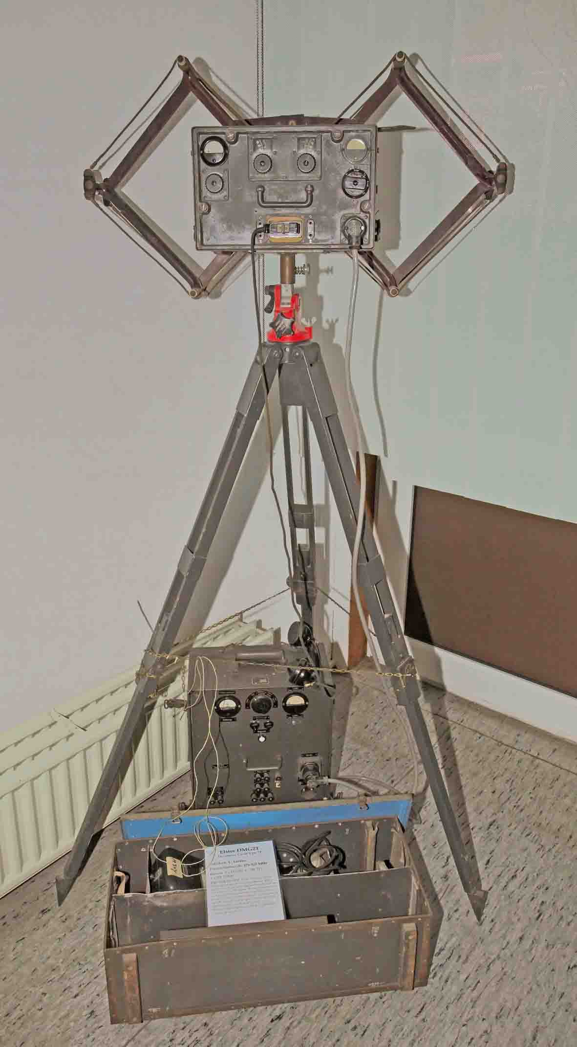
Decimetre telephone link on 475-525 MHz. Could also convey telex signals. Situated next to the entrance. (Photo taken by Gerard Vos on 21 March 2009)
Next to it

LiSpr 80 (Lichtsprechgerät 80 mm)
Since 18 June 2009 we have added a fourth display table in the rear exhibition room

The small Siemens & Halske corner

On the left hand-side we see the Siemens noise and interference search and measuring receiver type StmG 1867 and attached Su.G. 1868 (Störsuchmessgerät) On the right hand-side the Siemens & Halske LoG1 (Luftfahrt Schleifen-Oszillograph Type 1). The latter is a 4 channel current-loop oscillograph. It is designed to be deployed in aircraft (24 volt) and it could record simultaneously 4 channels. Current-loop modules are rather sensitive and can record events up to several kHz. The result is stored in a film-cassette. Timing markers are also provided and being 'flashed' at the film strip. We have to think, for example, of - measuring temperature versus pressure, or strain - temperature, in- and outside an aircraft and that like

On the left we see the Siemens & Halske LoG1 now visible from the film-cassette side, next to it the noise and interference test set. The small opened lid gives access to the facility where we can connect an electrical motor, for example a vacuum cleaner. By this means, the attached long and medium wave receiver can measure the interference level spectrum, calibrated in µ- and milli-volts

Display of various instruments
Philips laboratory wave meter of July 1944; R&S wave meters 90-800 MHz; S&H mV LF meter; H&B hot-wire RF antenna current meter; Wespe 2 (transponder), RS 3 and RS 7 balloon sonde; Gossen - H&B - S&H Bakelite meters
My wife made in spring 2010 a panoramic photo assembly as a result of here Photoshop exercises
Shown is our valve exhibition

From an artistic point of view she also modified the previous photo in a kind of negative print

The impression might be given that the artefact is displayed in a glass case
The Freya receiver also known as NE-Gereät.
We possessed already the power supply to Freya or Seetakt and have moved it from the MLK display to the Klooster exhibition.

Freya/Seetakt power supply unit, with on top of it the RX/IF module. The blue coloured class window is to filter the ultra violet spectrum of the two mercury rectifiers (please see Exhibits details). The horizontal glass window on top of the power supply unit (Netzgerät) is covering the multi meter voltage and current controlling section. The two selectors just down of it is for regulating the mains and the right one is for adjusting the HT of the transmitter.

On top of the just visible power supply of Freya or Seetakt radar is displayed the Freya receiver with integrated IF module. The power supply is a rather heavy apparatus, of which I guess its weight is more than 150 kg. The glass envelope in the upper section of the RX/IF module is the Stabilovolt type STV280/80 voltage regulator. The upper voltage regulator has a central hole, which allows you to watch its operation (acting as voltage indicator). Please see for apparatus details: Exhibits details
In June 2010 we were also able to obtain an extra KWEa which we have removed from its case, as to show how beautiful Telefunken engineering had been

LWEa / KWEa (on top)
On top of it you see the similar KWEa receiver type, though, now "inside out". I believe that the KWEa (and LWEa) receiver was one of the most elaborated receivers of its kind. Its coils turret is really a master piece of engineering. Interesting is that the black Bakelite rectangular device, a bit down at the far right of the chassis, is the dual quartz crystal; the small box contains two quartz crystals (flex-mode types), one for 250 kHz and the second one for 251.8 KHz (upper and lower sideband). However, by engraving the latter text they have made a mistake - instead of putting 251.8 they engraved 521.8. This was corrected by a second approach. Please notice for receiver details: “The significance of German electronic engineering in the 1930s”
(new)
Very recently someone from the UK donated very kindly the wavemeter belonging to the Berlin radar system (FuG224 - FuMO81) to become part of our collection.

In the background is shown this so-called "Hohlraum-Frequenzmesser" type Rel mse 2032a
Please click for details on the: Rel mse 2032a page
On 27 October 2010 we have reshuffled two exhibit tables.

In front we see the outstanding driver stage of the nice AS60/M1K transmitter, adjacent we see the newly obtained Schwabenland receiver (Ln21012), albeit without its case. This receiver I have swopped with Ebbe Peedersen in the late 1970s. I then swopped it with Hans Evers (PA 0 CX). As he is now over eighty years old he was so kind to let me re-obtain it

The Schwabenland RX (Ln 21012) is shown on the right and on the left the AS 60 driver unit. Previously we showed on this place the valve testers RPG1 and RPG2, which are now interchanged with the AS60's previous place. I have to apologize for the fuzzy spot at the front panel of the AS60 module. It might have been caused by a lens reflection

Our new display showing in front the Schreibmax MZSE (Enigma text printer). In the background we see the power supply to it type MZSS. Its cover has been removed and is shown below and the opened MZSS module is hanging at a wooden frame. This is the way it was originally meant to be mounted at a (ship- or room wall)
On 5 March 2011
We have decided to change the display at the rolling tables.
In my perception it is making sense to bring not yet shown artefacts on display, as measurement technique is also a point of interest. However, showing measurement apparatus in the way they appear on a shelf is not very attractive. That is why I have chosen to show what actually is inside boxes. This aspect is also in line with one of my future plans - where I would like to bring an "aspect of art together with not visible aspects of technique". My aim is to call this kind of watching "Inside out". The artist might notice some details of technique which has no technical means at all though, which can express visions that is coming to us via the means he is looking at these aspects. Thus no longer explaining what it is - but translating his vision into combinations of unexpected dimensions.
I have to apologise for the materials in the background, which are temporarily there due to our Würzburg (final) cabling work. Please notice section T and U of our Wurzburg-rep page.

This is what you will see first when you enter the rearranged rear exhibition room

Standing with your back towards FuG101/ Würzburg
On the far right R&S (PTE) Leistungsmessender SMLK for 10 - 100 MHz (please notice also 'Exhibits details'). Interesting is that it employs 2 x RD12Ta - 2 x EF14 and 1 x RD12Ga (the latter valve measuring the output level). Left from it on the same table, PG105 a Gema radar test set for IF and HF frequencies. Left of it, at the left moveable table, Siemens & Halske LOG1 (Luftfahtoszillograf). An aircraft loop-current-oscillograph (data recorder), its 4 channel measurement is being monitored by means of a broad size film of several metres long. A flash-light is triggered by means of a mechanical timer unit, as to provide the recorded time reference (scale). On the far left the R&S (PTE) antenna capacitance measuring set ACR.

Continuing our clockwise rotation, standing in front of the WT40 set up, looking towards the centre of the hall
On the table in front we see on the left the R&S (PTE) antenna capacitance measuring set ACR, next to it LOG1 this time we show what is inside the main unit and its mechanical timer; very intriguing mechanism. On the table right in succession - PG105 Gema radar test set and its cover-lid which holds a coaxial test cable as well as a pair of headphones. And on the far right the R&S (PTE) power signal generator (10-100 MHz).

Rotating further clock-wise
On the left we see the Siemens & Halske low frequency spectrum-analyzer Rel mse 2030a and the Rel mse 2030a manual, this time opened; its mint state and proper construction is evident. In the centre the noise search- and test set SuG 1868 - STMG 1867-1868 See also old archive displays; on the far right the R&S (PTE) VLUK HF admittance meter 10-100 MHz.

The transportable Radione wireless station RS20M and R3 including their transport suitcase is moved to the display rack of the room. The artefacts which were displayed formerly have been moved to lower shelves

In the centre we see the Frequensmesser (wavemeter) a (K126SII - K126Rö - Fremess a), which has been pulled partly out of its die cast housing. In the background we notice an open WIQ (Bordfrequenzmesser), a R&S high precision wavemeter, which is standing on top of another WIQ (only having a different wave range, but both constructions are equal). Like WIP and WID their principles are being based upon a course wavemeter (covering the entire range) and an ultra accurate frequency generator. Covering a small range which is controlled against a 100 kHz quartz. In case of WIP the spec of this generator accuracy is 0.005 %. I guess that WIQ is providing a comparable precision; its internal construction is very sound and is still in a mint condition. On the far right we see the Siemens & Halske Rel send 7a signal generator with its top lid opened. This, by the way, is a rather good HF generator with a calibrated (defined) signal output, which is being controlled against a 'thermo-couple' (Thermokoppel). When you listen by means of a separate receiver to the tuned (oscillator) signal with top lid open, the signal will disappear when it is being closed. This is due to the sound way the lid is being grounded by means of special copper strips and other means. By the way, our Type numbers wizard was of great help to me as it eased the search on this website as to find the many direct file links!

Watching in front the Neumann level meter (Dämpfungsschreiber) Rel mse 124a. In the background we see the left-hand side of the S&H LF spectrum analyzer (noticing a part of the filter-banks and the power supplies) . Upper left we just see the very high quality coil arrangement of the R&S (PTE) WIQ wavemeter (Hescho silver deposited ceramic coils please scroll down for the 'Ring-Spulen')
I trust that you will agree upon that showing what is inside a magic 'black box' is also having its own charm. This aspect is making this technical period so interesting. Nowadays one is no longer able to predict the purpose of a printed circuit board, as they all look more or less similar. Only the implemented (embedded) software is directing its purpose.

Köln E52 dismantled
Our attention is now focussing on the wiring board (BUS) of the Koeln E52 series. On the right we see the tuning capacitors of the receiver which are "underneath" the coils modules. Please notice that the simple wiring inside the central board is the only interconnecting wiring of the E52 types! This Koeln receiver had been previously on display in the rear hall, but was removed from there as to give space for the 'inside out' exhibition. Although, this display is also of the same kind, it was felt that visitors were not really noticing what the Köln wiring and modular concept is about. The Schwabenland RX has moved to the Naval corner.
(1)
In the beginning of April 2011 Gerard Vos did send me a CD-Rom containing photos which he had recently made during his visits on 11 December 2010 and on 19 March 2011
I instantly selected the next photo which shows the transmitter type: G1,2K (Swiss momenclature), also known as: 1,5 KwS b

On the right hand side of the transmitter we see the heavy three phase power supply (about 450 kg!) to this transmitter. The small frame on the left hand-side of the transmitter frame is the original electrical station heater. The dark box right of the Morse key on top of the transmitter is called: Trägersperre a kind of VOX, type TSp2; which is opening the transmit channel when a voice or tone signal is activating it. Thus, the transmitter is being switched on and off semi-automatically when a voice or tone signal arrives via a telephone line. Hence, it responded on tone modulated Morse signals as well. (photo with courtesy of Gerard Vos, Waalre NL)
About 1983, by a very fortunate constellation of stars, my good old friend Dick Rollema (who was a member of our Foundation Board from the early beginning in 1994 up to November 2010) visited Switzerland. He and his wife Fien were both guest of a "Ruderverein" near Luzern. Dick was sitting next to Mr. Odermatt who was in those days responsible (in charge) for selling-off obsolete Swiss Army material. For what ever reason he spoke about his radio hobby, and he might have told Mr. Odermatt about my interest in German communication gear. However, I was able to purchase a complete wireless station for the metal scrap price only. Of which they had still two complete stations in stock. By the way, these kind stations have been, maybe for decades, belonged to the their strategic stocks, as was the case with most of the Swiss Army equipment, before it was ultimately being soled-off. However, one station should go to a Swiss museum, the other one was not yet decided upon. I was charged for 50 Rappen per kg (= 0.5 CHF). Please bear in mind, that all together weighted I guess about 1600 kg, including a 17 m telescopic antenna mast – RX E44 and many auxiliary and spare parts as well. How I managed getting it all in Amsterdam, is a separate story. Nevertheless, showing this nice transmitter in working order, where both transmitting valves RS329 are glowing dimly red is often the apotheoses of the day. The generated HF power is for this occasion being absorbed in the three 500 Watt bulbs on top of the transmitter, as to prevent unnecessary H.F. radiation.
On 15 April, Anton Kroes and Maurice Hünen visited our collection. As usually, we switched on the G1,2K (1,5 KwS b). Maurice took the next two photos.

The two RS329 power output valves blossoming dark red during the time the transmit key is being activated

After the transmitter had been switched off, I pulled the keying module (Tastteil) out of the main frame
The two power valves are type RS282, these valves are keying the negative bias of both RS329 power output valves. The moving coil instrument is indicating the line value of the keying current (indicated in mA). At choice originating from inside the transmitter or provided by means of a telephone connection (remote keying = Ferntastung). The wheel on the right hand side is for selecting the transmission mode, like: Morse A1 and A2, A3 AM modulation, and facsimile. The black control knob on the left hand side is to adjust the transmitter output power.
Noticing these photos you might understand why seeing this transmitter in operation is so attractive. The way it had been constructed reflects the state of the art of, say, 1937-1938. Mr. Odermatt told me once, that its reliability, as a post war jammer transmitter, was very high, and defects occurred rarely once in a few years of its operation.
From England we obtained in September 2011 some interesting materials, being artefacts and papers.

On the left the complete Jagdschloss transmitter and on the far right the Gema so-called X-Gerät (please notice for more details our Jagdschloss page)
The latter is to control whether the Seetakt transmitter and receiver are both tuned at the same frequency, without the necessity of watching actual targets. As the not existance of targets could also been caused by the fact that both are not aligned against its other. (Please notice for more informations: Exhibits details page 3, and also: Gema X-Geät and system)
On Friday 7 October someone very findly donated to us a Fremess a
This is a widely used wavemeter apparatus,
In its specs and performance comparable to BC221
It has 20 bands covering 30 kHz - 30 MHz

Just left of the old version K126 Rö is the new Fremess a
Please see for more details
On 12 November 2011 the crate from the US arrived containing:

FuG136 Nachtfee apparatus
Please read for a new survey: FuG 136 Nachtfee
On 3 September 2012
The Nachtfee system now more or less hypothetically operational, is getting a new setting; as the previous set-up in the rear hall disturbed too much the existing displays. The consequence is, however, that some artefacts had to be arranged newly.

The Jagdschloss transmitter, equalling the regular Freya transmitter, albeit providing more output power, had to make space for the FuG25a test set-up arrangement
In the background the Lo70KL40 is displayed

We must admit that the red fire hose is not the best setting, though, we have to cope with the fact that free space is valuable. This setting is, nevertheless, logically quite appropriate
On the right: on top of the Freya/Seetakt power supply the Freya receiver/IF/Video module. The top module is very kindly on long term loan from Jan Wolthuis (PE 0 RTX)

The Nachtfee ground console displayed in a more definitive setting just opposite the simulated FuG136 aircraft system. This new setting makes it possible showing what the consequence of Nachtfee 'orders' or commands will do at the simulated aircraft display
The interactions between the Nachtfee ground console and the simulated aircraft system is handled fully by means of wireless signals bridging a distance of say 2.5 m.
Please notice that the Freya modules shown on the left-hand side is more or less what was the case during wartime days. Nachtfee was a part (section) of the so-called Freya-EGON system. Bearing this in mind, the setup next to our Freya units does thus make sense.
On the right, next to the Nachtfee main frame, on the wooden mounting we see the EGON ground receiver. Code-name: Gemse This is receiving the two signals returning from the FuG25a system. One being the 500 Hz EGON signal pulses, the second signal representing the actual time-base (circular) deflection phase. The Nachtfee signal phase should be matched with the one in the aircraft. This can be accomplished by means of the so-called 'Phase' control on the Nachtfee front-panel.

On the left is the replica of the FuG25a (IFF) mounting. On the right the simulated aircraft display
On top the synthesiser, which is providing the appropriate time base signal. This must be adjustable as long as the Nachtfee quartz reference has not yet reached its equilibrium. Until now, both references never reached this state entirely.
The HP scope CRT is painting a circular trace which equals the control CRT (LB2) build-in the Nachtfee frame (on the right hand just above the 'order' compass.
On the shelf the 24 volt power supply for the FuG25a IFF transponder; which is handling both EGON, as well as the Nachtfee 'order' signals and is retransmitting the time-base-phase towards the Nachtfee ground system.
Please be aware that these simulations are purely hypothetical, as no original documents have yet seen daylight again since 1945/46.
For additional information please also consider:
Please notice that its latter content is about 6 MB! Slow internet may cause too long delays
On 15 April 2013
Page actually initiated on 24 May 2013
As a preparation for the soon coming Open Day on 20 April:
Jaap Keijzer was so very kind to prepare the cables which fit onto the Liechtenstein SN2 apparatus (Li-SN2) operating copies of the genuine coaxial connectors. Which being designed particularly for this type of coaxial cable (70 ohms).
It has to be noticed, that these cables are being kept for practical reasons shorter than they practically should be. Normally these are fit and adjusted as to create a match in respect to wave-length; in most cases being ½ λ reduced by the velocity factor of the operated coaxial cable (this 'blue Vacha cable' has a v = 86! due to the fact that its dielectric is mostly air), as the circuitries are virtually not seeing a regular cable mismatch*. Of course, still losing signal owing to transformation, but the circuit is for HF still matched correctly. * For instance, always two antennae being interconnected in parallel reducing 70 ohms into a 35 ohm load (70/2), which has to be matched onto a 70 ohm load again.

The current Li-SN2 setup

Viewing the cable connections a bit more in detail
Not all cables being connected, as it does not make sense and is costing valuable coaxial Vacha cable; which is nowadays hardly obtainable. As this system cannot be demonstrated without HF radiation, it was decided not to wire it. For your information, the four antennae cables being omitted; with the single exception of the top one in the centre. As this one is being demonstrated as the genuine predecessor of what became known as an F-Connector. This may be an example of captured enemy intellectual property! I was unable to trace yet the according patent, which doubtless must have existed on behalf of Telefunken!
To be continued soon
By: Arthur O. Bauer
Go back to, or proceed with: Exhibit details
Go back to, or proceed with: Exhibits details 2
Go back to, or proceed with: G-Schreiber T52d information
Go back to, or proceed with: Exhibits museum registration
![]()