
Nachtfee
a
Confrontation
(eine Auseinandersetzung)
This chapter is confronting ourselves with a US post war report on Nachtfee
Page initiated on 13 July 2017
Current Status: 5 September 2017
1** + 2 + 3 / 3a + 4 + 5*** + 6
Please notice that since 5 September 2017 also some additional YouTube films have been attached
*** On 28 August 2017, after due considerations, I have decided to change the signal loop drawings, as to improve better understanding
U.S. Naval-Technical-Mission-in Europe
Declassified
By Authority NW 5448/
Technical Report No, 520-45
The "Nachtfee (Night Fairy) System for Ground
Control of Fighters
October 1945
U.S.-Naval-Technical Mission-in-Europe
To us our first impression was very promising

What can we learn from file page 2?
That its issue date was 26 October 1945
It was signed by: L.V. Honsinger Captain, U.S.N. Acting. He isn't the author of this report
Also some addressees are noticed, like:
CUNO (OP-16-FT)
CUNO (OP-16-PT)
FIAT (known to us from their reports)
Office of Research and Inventions
Naval Research Laboratory
and, to me, some mystic others.

Document section page 3
My revised approach to this subject.
Digesting the document pages, my first thoughts were a tough response; but I have deleted my preliminary comments; and have reconsidered it mildly.
Honourable Mr L.A. Gebhard found on the web, later became a quite famous person.
My dilemma, however, in mid 1945 he proved to be lost in the Nachtfee subject, I therefore have decided to reproduce some pages and don't correct every sentence, because this webpage would consist of corrections mainly.
I my perception, it would be better to leave the page reproduction as these are, and on the other hand letting you understand what Nachtfee really was about.
Why do I consider myself competent to appose Mr. Gebhard? Please - judge it yourself.
For it I would like to go back to January 2005. Willem Klein e-mailed me an Ebay link, in which he asked: do you know this device? First telephoning some German colleague collectors, but they had seen the offer as well on Ebay, but also had no idea what it might concern. Confused also by one photo noticing a: Freya-Polwender plate.

The genuine reproduction of the 2005 Ebay offer
I did put in a bid of 250 U$, apparently someone succeeded mine.
I forgot it all, until September 2009, when Phil Judkins visited me - in Diemen - for working on our mutual presentation on EW. Among a pile of papers he brought along, was a document called Radar News 19, an Allied translation of a German radar periodical Funkmessnachrichten issued on 25 February 1945. On its last page I encountered:

Quite understandable that my breathing hampered!
But, the Ebay offer went back to 4½ years ago. In a desperate move I created an additional webpage titled: Wanted! combined with some photos, which I luckily could retrace.
After about three weeks I received an e-mal with: "I have it". Fine we were in touch. However, it proved to be rather tough, and with mediation of a French/American friend Brian Thompson, Ni6Q, ultimately, on 12 November 2011, an "air cargo" crate weighting 95 kg arrived.

Nachtfee designated CT 3379 (written red chalk) just arrived in our Museum (photographed on 12 November 2011)
Lacking both CRTs, one, on the left-hand side had been put in temporarily, just before this photo was taken.
It is clear that its appearance was, though, quite shabby.

This genuine photo is found within the US report
Clear is, that the two CRTs were already removed in 1945, and the consignment number CT 3379 shown in the foregoing picture has not yet been attached.
We have proved, that this device had been sabotaged, likely by the Germans, as it was done just very tricky. Hence, in the US they have never tried to let it function, nor have they investigated it internally, as crucial seals weren't yet broken.
Therefore, we should consider that Mr. Gebhard likely once had been instructed to provide a brief report on some (unknown) captured technology, but hardly with the aim going into it!
However, it took me several years of considerable commitments - but it resulted in the hypothetical reconstruction of the entire Nachtfee guiding system, including the (hypothetical) aircraft order presentation. Albeit, hypothetical, but entirely HF operational (bridging three metres instead of 250 km). However, all system parameters taken into account; even in respect to EGON signals; operating a common miniature transistorised HF modulator/transmitter.
A complication for Mr. Gebhard must have been - the absence of knowledge of what some German technology is about; particularly on what he named Freya radar.
We all know, what radar is about, but maybe forced by the circumstances of war, they adopted systems which weren't employed elsewhere.
Radar generally has a range limited by physical factors; in case of Freya this laid between 100 à 150 km.
In case of Nachtfee, they necessitated a farther reaching capture range. Of course, the Germans possessed radar with wider range, such as: Mammut and Wassermann.
But Nachtfee was a system relying on guidance over at least 250 km, possessing a rather narrow aperture. The advantage of Freya versus the huge other systems was its mobility. It could be erected everywhere in short notice.
For it they headed their guiding radar stationary beaming just kept over the aimed target.
At a certain moment, likely coincidentally discovered, they started to exploit their I.F.F. transponder type FuG 25a. Radar signals have to bounce at metal surfaces with loss through dispersion; in contrast, exploiting the I.F.F. transponder increases range up to, or even a bit beyond, optical range (line of sight). This technique later being designated secondary radar.
The advantage of all Freya systems, was, that these all used 500 Hz PRF; and they had, for practical reasons, already standardised their I.F.F. operating at 500 Hz PRF as well. A great advantage implementing EGON was, that it became quite simple to integrate EGON within the regular Freya outfit. Their range measuring delay-lines could be employed straight away for EGON operation as well. Sadly, there is rarely documentation around its actual circuitry integration.
They coined the acronym: EGON Which stood for: Erstling - Gemse - Ortung und Navigation (code-word for the FuG 25a transponder - code-name for the ground receiver - DFing -and- navigation)

A basic idea what Freya-EGON in combination with Nachtfee was about
The FuG 25a I.F.F. operated with vertical polarised antennae
Therefore - EGON operated with vertical polarised antenna-arrays
In the course of the war, Freya systems tended to operate horizontal polarised antenna-arrays
What I cannot judge, is, whether once EGON systems have been utilised with an entire Freya frame fit with vertical antennae; otherwise the EGON system had to rely on a (smaller) array on top of the regular Freya antenna frame
Such I.F.F. arrays were utilised for quite many decades after the war
Considering all this - is the usage of the word Freya system nonsense!
However,
We later will notice that EGON signals behaved "incoherence" within their own system, but 'none' in respect to Nachtfee, also the inverse was true.
Maybe providing less accurate range data, but to what is known, they could, at will, operate in split-beam-mode too; providing highly accurate bearing information.
It is theoretically possible to operate the regular high-power TU 100 transmitter. But what is known, in bigger radar systems, is that they utilised two quite equal transmitter frames (modules) providing each one about 8 kW pulse output. Whether this was accomplished in the Nachtfee related circumstances we don't know.
The smart idea on Nachtfee was, most likely, invented by T. von Hauteville, from the GAF research site Rechlin (80 km north of Berlin); who was also the one who invented the principle of the Y-System (Britons designated it Benito).
Both, Nachtfee and the Y-Systems, relied upon measuring signal-phase-shift, passing through transponder systems.
My dilemma, I knew Fritz Trenkle personally, but he passed sadly away before I came in touch with Nachtfee; he had passed away on 16 March 1996. On the other hand, it is doubtful that he could have add more than he had published. I suppose that then T. von Hauteville was no longer among us.
Fritz Trenkle got, likely off the record, from famous R.V. Jones - as a gift - a copy of a then (still) kept confidential Felkin document- getting Trenkle's reference [101]. In his preliminary publication of 1966, on behalf of DEGON, he added complete rubbish to what [101] is about. Though, after, say, mid 1970s, after most restrictions in Britain had been lifted, he since correctly referred to Felkin Report. Which still couldn't be traced, because the way it had been catalogued at Kew did not pointed onto the appropriate direction. A portion of good luck, and persistency on behalf of my friend Phil Judkins, brought finally a huge bulk of Felkin interrogation reports to see daylight again.
In the course of my Nachtfee Survey, I could see, sometimes, where interrogation created rubbish. For example: an interrogated PoW might have once seen how Nachtfee was operated, but didn't understood what he actually saw; he stated: that first the conveyed Nachtfee order pointed moved outwards and secondly signal start to rotate inwards. In one word nonsense! The Perspex outside pointer was connected only onto a cam-wheel and a spring load, nothing else (see below). Its purpose, simply: a command (order) was passed on from the Freya-EGON crew - say, 5° to the left; first the outside pointer being rotated and set at the later to be conveyed order or command; thus acting as an order-memory only! Thereafter a certain procedure had to be gone through ending up with setting the shorter (Perspex) pointer in line with the memory pointer.

Shown: the only mechanism loaded onto the longer Perspex pointer!
Another problem constituted the absence of understanding on behalf of Mr Gebhard: in particular the lack of understanding of the implications of dealing with coherent- and none coherent signals. An essential implication of EGON and Nachtfee's techniques.
Is this really so essential? YES!
For example: Nachtfee did sent his commands or controlling signals, being a 'guest' on the Freya-EGON I.F.F. signal carrier (albeit, originating from the same pulsed transmitter). Therefore Nachtfee was equipped with 10 quartz controlled channels just differing: 2, 4, 6, 8, or 10 Hz up or down 500 Hz. Hence, not equal to the EGON signal PRF. Coherence made these systems insensitive against none coherent signals. This was a two edged sword; EGON wasn't interfered by Nachtfee signals and Nachtfee was not jammed or interfered by EGON signals! You can notice the (other) none-coherent signals on the pained trace-lines as background dashes, whilst the coherent signal stays steady.
Another shortcoming of Mr. Gebhard's report, is, the entire lack of understanding of the implications in the 'domains of time' (phase domains). This latter implication caused me difficulties to grasp what Nachtfee's system once was about; maybe, my own shortcoming - understanding this aspect. Creating a theory, waking up at night, thinking some circumstances over - what happens in case of something, and I had to go through it all again. This process of engendering is worth going through.


I would like to interrupt reproducing these page series, as it explains often are beyond reality, partly owing to reasons explained previously.
I would therefore, exclusively, like to explain Nachtfee differently, based on understanding build up over nearly six years of intense commitments.
It is inevitable to go a bit in to the concerned technologies, but will try to keep it, nevertheless, understandable for most of you.
Nachtfee generated at its output a sinusoidal signal, which signal phase being manipulated such that once shown at the FuG 136 or FuG 136a aircraft display the screen order blip being equal to what is set on the Nachtfee console compass; thus the system repeats orders or commands on a dedicated aircraft display.
The implications are most curious. Causing a single phase shift thereafter, theoretically, no one can notice that once the continuous running sine-wave had been shifted in phase. 16 orders means 360 : 16 = 22.5 degrees for each commando; thus every commando is a multiplied vector of n x 22.5 degrees.

Let us consider first the Nachtfee's basic circuitry
It is necessary, without bringing the proof, to explain a noticeable feature of Nachtfee, and that the entire concept, is relying on the application of three phase-shifters; by witch means, at will, a sine-waves can be changed in signal phase between 0° - 360° (n x 22.5°).
These goniometers are actually miniature selsyn repeaters, but being operated entirely different; the rotated search coil is acting as a signal phase-shifting device; the distributed magnetic field components being fed with three-phase 500 Hz.
What are their purposes?
Let us consider first the lower, designated 'Number or degree' scale.
Its purpose was first not understood.
About February 2012, there was no direct progress and I started to imagine about some theoretical aspects. Known already was that the Nachtfee's PRF is 500 Hz and consequently possessing a λ = 600 km, in radar terms 300 km. In a flash I became tantalised - might it be that the 'Number scale' dial meant 0 - 300 km?

Heureka!
Let us assume that the dial being set at 288 km.
Now it becomes clear where the mystic dial once was meant for.
Following the lower blue circuit line, we arrive at two CRTs, whatever there function might have been.
It was supplying time-base signals onto two different cathode ray tube types (one type dual-trace, the other one circular deflected).
** New considerations on 30/31 July have caused me to expand the explanation as to how exactly 0° is to be determined and their implications.
Therefore: first I would like to copy a photo of chapter 4:

Please notice the non linear (painted) time base line
The none-linearity, in the foregoing photo, being caused by the sinusoidal nature of the time-base signal source.

A wonderful example what actually is happening with the two painted time-base lines within Nachtfee, and its causing none-linearity; and accompanied projection.
Remarks added on 31 July 2017
Shown, actually, is the time-base-line-projection in degrees, which does not represent the actual signal-phase status of the Nachtfee timing. Nevertheless, it covers, say, 180°, which represents a range or distance of 150 km (300 / 2 = 150); therefore, it isn't always easy to adjust the signals precisely back-to-back†.
Please notice on the next photo, that both: the (painted) time-base-lines (albeit, that it seems that only a single being painted) and the signals at its centre operate in-coherence; that is why presentation behaves stable (neglecting, for this occasion, aircraft movements).
The adjustment - getting the returning (order or command) pulses adjusted at 0° is accomplished by means of operating, manually, range off-set (number scale, shown on the fore-last photo; also designated, in an explanation, "Phase Control C") such - that both the upper and lower pulses are aligned just back-to-back. Its 'nature' is (also) shown on the YouTube Film 60, just a bit down.
This could have been done at any order or command 'signal vector'. But this could, consequently, have been rather confusing (the order pulse being divided, at will, between 0 - 360°, but the operational range is also part of 0 - 360° signal-phase, but representing the operational range of 0 - 300 km!). Therefore, in my perception, it should have been done when the 'order or command' pointer is set at due north; or when Freya-Polwender being operated, at due south. In its North position the 'order or command' pointer being kept in a steady position, due to a "soft-lock-mechanism".
The sharp pulses visible on the centre of the 'dual-beam presentation' - are equal, albeit differently presented - to the pulse shown on the circular LB2 CRT screen at 'due north'.
On the other hand, circular - first-order Lissajous - do not suffer from linearity errors, as long as these being the result of sound sinusoidal waves projected in an appropriate manner; our circular LB2 presentation is just accomplished by this means!
† For this reason, I haven't operated the dual-beam presentation frequently, as the aim of the Nachtfee system was (is) to repeat the 'order or command' that has been sent towards the flying platform on the LB2 circular CRT screen; doing so by setting 'range off-set' control (number scale) accordingly. My hypothesis: it is not unlikely, that they once have -operationally - relied more on the LB2 screen presentation than on the precise dual-beam CRT alignment; the main range-track was controlled by the EGON system anyway.
continuing again with the main text:
Shown better in the next photo, we deal with two time-base lines (bear in mind that we operate a double-trace CRT). One the, what I designate LR - writes its trace from left towards the right; the second time-base trace does it from right to the left-hand side of the CRT. Both time-base lines being aligned such that you notice only a single painted line.
Like almost within every GEMA related system, the linear time-base-line is "employing the linear section of a sinusoidal wave-form" (thus no 'saw-tooth' signals being employed).
However, what these have, in the Nachtfee's concept, in common, is, that both crossing 0° at the same instant, albeit into opposite directions.
The most smart trick is shown in the next photo:

In first instance the purpose of this display was not yet understood (Dual beam CRT)
Just where both vertical lines in the centre match onto their time-line is found exactly 0° mutual signal phase!
Nachtfee testfilm 12 This YouTube film provides somewhere a good example of its adjusting to one another (albeit, that its content is later also dealt with).
and
Testfilm 26 Viewing the dual beam CR tube HRP2/100/1,5(A). The pulses in the centre above and under the time-base line has to be aligned such that both pulse becomes back-to-back. This does not yet tells you whether phase alignment is carried out at 0° or at 180° phase difference. The maybe visible flashing pulses originate from the simulated EGON signal, which is having a different PRF than used in the operational Nachtfee (not valid for channel Q5, because this is providing 500 Hz PRF as well).
Let us continue were my text had been interrupted:
First it did malfunction. The reason was found after technical considerations. The deflection section once had been sabotaged! But not in a crude manner but rather smart.
After having found where (not instantly noticed) two de-soldered wires should be connected (onto where was, sometimes, a guess) and it started to function since.
Although, it still wasn't understood how it worked; nor how it should be aligned to one another.
Incorrectly described by Mr. Gebhard, painted are two beams of equal properties, albeit one painting from left to right, whilst the second beam writing from right to the left (at the same time).
However, the two vertical deflection plates being inversed (cross) interconnected. First I had for myself to determine what might have been the appropriate way accomplishing it.
This presentation, also mentioned in Gebhard's report was found the optimum.
When you look closely, you will recognise that both baselines are equal but reversed painted.
The purpose was, to adjust the centre line phase against the previously shown range off-set; because when incorrectly adjusted against the returning transponder signal, the back-to-back projection does not match; shown is correct adjustment. (will be shown in the next YouTube film)
But there exists another CRT this one is of the circular deflection type (LB2)

This, in my perception, is the most smart feature of the Nachtfee system
Let us consider first the blip, or signal, pointing at due North. A rather common starting position of operational Nachtfee.
But this signal does not originate from inside the Nachtfee console, but arrives via the FuG 25a aircraft transponder - returning through the Gemse RX on the ground. Its signal phase is, of course, being delayed in time by passing the operational range twice (0 to 360° demands a λ or range of 600 km, though in radar terminology constituting 300 km) . But now the range off-set control coming in force. Its dial being rotated until the order blip equals (repeats) the order pointer vector set on the Nachtfee compass scale.
How smart!

The order or command compass
The actual order pointer (the shorter one) set a due north.
However,
The solution for manipulation a single phase-shift and being always in the position to reconstruct the entire system values is indeed striking simple. Of course, the range off-set has to be controlled continuously due to the movements of the guided flying platform. Such single phase-shift being commenced by means of setting the shorter pointer at one of the 16 designated commands.
Let us, for now, neglect the appearance of the second blip at, say, 8 minutes passed the hour, albeit that it vector is also a crucial parameter of the Nachtfee controlled system.
I would like to repeat the foregoing implications using a more principle block diagram.

The foregoing processing description may be better understood looking at it this new way
We dealt with the Range off-set phase-shifter designated C. Please bear in mind, that the origin of this signal originates from the output stage following 'controlling' phase-shifter A.
The signals shown on the two cathode ray tubes originate from the Gemse receiver output. You may remember, that the Gemse RX originally belongs to the EGON and I.F.F. system; where our Nachtfee signal is only a 'guest signal'; thus it originates from the guided pathfinder's FuG 25a I.F.F. transponder.
Bearing this in mind, we consider now the upper blue signal path which enters phase-shifter B. The latter constituting Nachtfee's command or order source. The scale of the 0 - 360° is build compass like, therefore I, sometimes, refer onto the 'compass'.
The output sine-wave signal is after passing through the Freya-Polwender switch, first fed onto a pulse modulator; as I.F.F., and radar like signals relying on pulsed signals. This signal being handled within the transponder type FuG 25a. But, just where the transponder receiver output entering the transmitter modulator, the Nachtfee signal being picked-up (actually at pin 9 of the test-connector). Logically the incoming signals (EGON I.F.F. + Nachtfee order) will be retransmitted onto the (Freya)- EGON ground system and also being transferred onto the input stage of the Nachtfee console again.

Consider, for this occasion, that you are watching the display inside a to be guided aircraft
The lower, at due south, blip could have constituted the "Freya-Polwender" setting
Please notice (in the next YouTube film) the flashes between the painted time-base circle and the CRT outside metal cylinder are originating from the none coherent EGON pulses. For this occasion, quartz channel 8 being operated; constituting 506 Hz. EGON operates at 500 HZ PRF, thus the flashes are 6 Hz in PRF differing and constituting no observation jamming.
Please consider the according YouTube film: Film 60 (0013)
Please notice: that the pulsing like presentation originated from about this period operating transistorised interface. Later in 2013, a modified valve controlled interface was implemented and signals since being shown constantly.
Practically this never could have been the case, because, the Freya-Polwender switch interchanges the two symmetrical output wires of the Nachtfee console (meant the appearance of to order signals at once). Interchanging connections normally does not causes a measurable difference; thus neglect the existence of due north blip, as long as the due south signal being there.
Why have they implemented such a Freya-Polwender function?
According Felkin, and incorrectly noticed by Mr. Gebhard, it should most likely have been maintained - as to inform the aircrew navigator that no order or command signal is present. When, however, the due south blip jumps to its regular due north position, the crew was alerted that with some, procedural delay, an order or command is to be expected. The foregoing YouTube film shows what it is about.
However, continuing with the foregoing LB2 screen.
For our eyes and brains instantly being showed at the according CRT screens; bear in mind that this appears 500 times a second.
Therefore it makes sense, that range off-set C being manipulated such that the LB2 screen matches to what the compass pointer is set upon. The signal phase-delay should equal: the time it took to be transmitted upwards - passing through the FuG 25a aircraft I.F.F. transponder and entering the Gemse receiver on the ground and finally being supplied onto the Nachtfee console signal input.
Please continue only - when you have grasped the forgoing explanations.
We haven't yet dealt with phase-shifter A.
Please don't be astonished when I tell you that operating this phase-shifter control: that nothing will happen on the Nachtfee two control screens.
Why?
When - signals originating from a common source following different signal paths - when these will meet again whatever time delay have taken place, they are still in coherence!
Quite understandable, tuning phase-shifter A will, of course, causing a shift in signal phase, but the off-set being equal for both (blue) signal channels; in our case: the order or command path via the aircraft transponder as well as the range time-base circuitry. Therefore, it doesn't matter what the actual setting of control A is.
There is no means existing within the Nachtfee apparatus, to control the effect of operating control A.
Let is imagine what actually is causing this.
Let us consider first another fundamental system parameter:
We have noticed that a Nachtfee command consists of a single-signal-phase-change. But how did they recognise it in the aircraft system?
This only can mature: when both: the Nachtfee and FuG 136 aircraft systems are operating an exact equal (running) time system; thus both 'clocks' running in concert.
Is this really possible? Not really, neglecting the relativity aspects, there do not exist equal performing frequency (timing) devices in the world; even not today. Albeit, that we have reached a technological standard where differences often being expressed in µs per year or decade.
However, the early 1940s hardly possessed these capabilities. Particularly not for military purposes.
This latter aspect might have been a crucial reason why Nachtfee in general use failed!*
* In late 2015 and early 2016, we have implemented a rubidium controlled frequency standard, combined with provisions were 15,000 Hz and 500 Hz sine-wave signals being provided. By this means of stability, of say 10-11, we have proved that it could have worked rather well; but this technology wasn't yet invented and thereafter it took several decades before it became miniaturised and affordable. This will be dealt with in a later chapter.
There existed, nevertheless, systems reaching the specifications of 10-9, but these weren't mobile and fashioned for the application within Nachtfee and operational aircraft at altitude of up to 9 km and even beyond.
But, technically they also came up with a controlling facility of the FuG 136 aircraft.
We have noticed that the main difficulty of the Nachtfee system laid in the "domains of time". No one could predict what the actual signal phase was within the Nachtfee system; in respect of range, as well, as phase-time.
Repeating the LB2 screen presentation again
But now concentration our attention towards the pulse at, say, 8 minutes passed the our.
The aircraft display operated an equal LB2 cathode ray tube facility. Where the painted circles being accomplished by means of creating a first order Lissajous figure.
Like in Nachtfee, the frequency divider circuits operate with sine wave signals. Therefore, without bringing the proof, when splitting up the sine wave in a direct- and one channel being shifted 90° and projected rectangular to one another - a circular, first order, Lissajous figure will be painted on the CRT screen.
The trick, feeding the sine wave signal onto a trigger stage where a pulse being generated just when the clock-sine-wave passing through 0°. This is, by appropriate layout just the instant where the Lissajous painting spot is at North (12 hour). This pulse being fed onto the transponder transmitter as well. Causing that three pulses will be send towards the ground; the I.F.F. signal + the responded Nachtfee order thereafter being used for range-off-set + the FuG 136 (aircraft) timing reference pulse.
The latter projected above at 8 minutes passed the hour. This vector is valid in our hypothetically reconstructed Nachtfee system, but guarantees that the overall Nachtfee pulse timing will arrive just in time for correct presentation on the FuG 136/136a aircraft display. In real practise, it might have been constituting another vector.
Thus, control A is to compensate for timing difference with the aircraft FuG 136 system.
Two questions: how do we distinguish between the returning Nachtfee order signal and the aircraft clock reference pulse?
We have already noticed, that operating control setting A does not have any noticeable influence upon the returning Nachtfee signal reference; in our case the signal pointing at due north; because this signal is in coherence with the Nachtfee timing.
But, the aircraft-clock-reference is not originating from the ground system and, therefore, constituting a none coherent signal, and will thus respond upon rotation of control A.
Quite curious, operating control A only the aircraft clock reference rotates around the painted line.
Please consider the according YouTube film: Film 59 (0027)
Please bear in mind: that the aircraft clock reference shown on the LB2 screen has already been compensated for the system parameter "range" therefore has the aircraft clock reference signal become a static system parameter.
Bear in mind, that the range compensation considered also the signal path upwards followed by the downward path!
When we consider this being a valid system description, then we should deal with my system hypothesis.
Changed on: 28 August 2017
*** Don't be worried, I will guide you through it

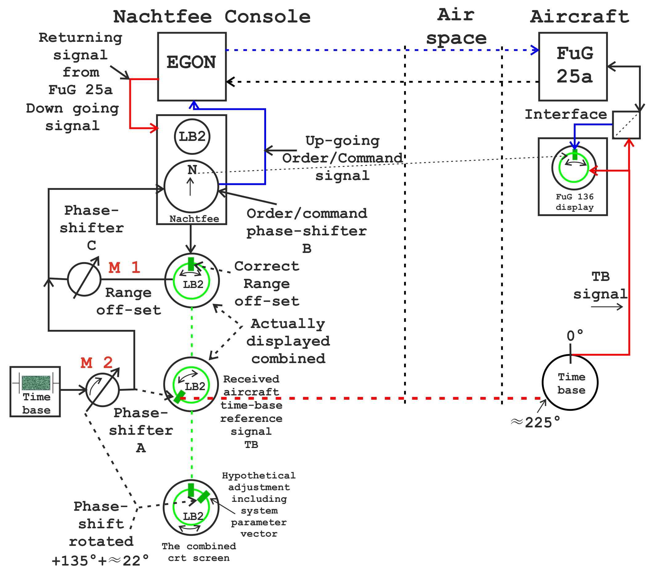
Analysing briefly the way the system being operated, we should take into consideration first - the two loops of system-control for both: EGON and Nachtfee
The EGON system-loop is quite simple to understand (following the none-dotted black-arrows): Freya-EGON sends its signal towards the FuG 25a aircraft transponder and its response will be passed onto the EGON control system.
By this means providing distance or - range data - between the ground station and the to be controlled aircraft (considering the time it takes between transmitting @ 124 MHz a pulse and its reception @ 156 MHz on the ground).
However, of more significance:
Our main loop starts just where the two signal wires leaving the Nachtfee console. It is being interconnected onto the Freya-EGON system; in particular the pulse forming stage driving the combined EGON and Nachtfee signal transmitter; whereby the Nachtfee order/command signal is "being handled like a guest", not interfering EGON's main (guiding) function.
From EGON - the signal passing through free space, where v = c at some instant being picked up at the main transponder antenna arrangement; at an average frequency of, say, 124 MHz. Thereafter being amplified by the I.F.F. transponder receiver; which output regularly enters the transmitter modulator stage. Just in between these latter two sections - signal being accessed at test-connector pin 9; from here it is fed onto a pulse-forming interface part of the FuG 136 or 136a aircraft system.
The second loop (shown next), follows an inverse route: from the aircraft deflection circuit - responding upon the 0° time-base pulse - being modulated and sent together with both the returning Nachtfee pulse + the I.F.F. transponder signal (dotted black arrows).
The I.F.F. output being retransmitted towards ground @ about 156 MHz and conveyed towards the EGON-Nachtfee Gemse receiver; from there the so-called video signal is fed onto: EGON- the other part conveyed onto the pulse forming input-stage within the Nachtfee console.
Thus, in my, hypothetical, perception: this preliminary explanation constitutes the first system loop understanding, consider it being the up-going order/command loop towards the aircraft display.
However, we also need to possess 'information' about the aircraft timing reference - what is, at a particular instant, its actual aircraft 'phase-time' (versus the actual Nachtfee time-base-reference)? Here we encounter also aspects of the 'domains of time' (phase domain).
Consequently: when no 'phase correction' being commenced - considering, hypothetically, all timings stay exactly in concert - the displayed Nachtfee order/command-blip will rotate anti-clockwise at the aircraft display!* Bear in mind: that when distance increases the Nachtfee signal arrival will, for every succeeding pulse, be received just a bit more retarded in time.
* Click at this link and a PowerPoint film (.ppt) will start running endlessly, until you press the Esc key.
Why?
Because the Nachtfee order/command signal will, due to aircraft movement*, arriving increasingly delayed.
* Considering the aircraft moves in a straight line away from the Freya-EGON location. Please bear also in mind: that Freya-EGON operates (here) a stationary guiding beam, where system-azimuth kept constant at a particular direction (vector) - for the reason, that its beam crosses, invariable, the aimed target area; thereby (also) obtaining Left - Right 'off beam-centre' information; of course, also distance being watched.
Hence, an additional control loop had to be implemented:

Considering the foregoing explanations - shown first is the up-going phase (timing) corrected order/command path, secondly taking into account the current 'phase status' of the aircraft time-base-reference
Consequently continuing:
For your convenience repeating the foregoing photo
Ultimately, the (returning) aircraft time-base reference signal - will appear, for example, like the signal at approx. '8 minutes passed the hour' though it is constituting a none-coherent signal; as it does not originate from (within) the Nachtfee console system. Its great advantage: it can, therefore, be distinguished easily by means of operating Phase control (A). Hence, the coherent signal (pointing at due north) will not be effected by operating phase-control (A).
This was accomplished by operating (manually) phase shifting control A; causing signal retarding or increase in the 'phase domain'. When accomplished correctly, the Nachtfee order/command blip being manipulated - in phase timing - such that it arrives just 'in concert' with the actual instant of the painted (LB2) CRT 'control' blip; herewith repeating accurately the genuine Nachtfee order/command signal onto the aircraft display.
In my perception (already dealt with in the foregoing two drawings): this loop runs from: - aircraft timing-system - towards Nachtfee console - there manually brought in line with system parameters (operating phase control A) - therewith manipulating the correct time-of-signal-arrival at the FuG 136-136a aircraft display.
(6)
On 5 September 2017
A few days after having contributed the foregoing system explanation, a new concept matured in my mind - which might enhance your system understanding.
It can, nevertheless, be helpful to keep in mind the just foregoing explanations dealt with. ***
The Nachtfee console internally relied on the manipulations of sinusoidal signal phase
For most of you likely curious - is the fact that operating 'Phase control A' can by no means be noticed directly at the two CRT control screens!
For it we should hold in mind, that the two blue system line circuits - the upper and lower line-sections - are operating in 'full coherence' to one another.
Why?
Because both originate from a common source following Phase control A. The upper path fed onto Phase control B, which, by the way, constitutes the Order/Command Compass. Varying its setting will cause a signal phase change accordingly signal-phase shift on the output wires. Which thereafter is being supplied onto the EGON system; and sent towards a Pathfinder aircraft; passing through the aircraft I.F.F. transponder type FuG 25a and being conveyed towards the EGON ground system (again). From there the Nachtfee signal is returning to the Nachtfee console input stage (as does the EGON signal). This signal being here symbolised by the yellow signal lines. Quite in a conventional manner fed onto the vertical deflection of the two CRTs.
The lower signal path constitutes the horizontal deflection (time-base) signal. Albeit, that the LB2 control CRT is of the circular deflection type.
Let us consider, for simplicity, that we receive a signal pulse. Operating Phase control C causes a phase shift and the received Nachtfee signal will virtually move along the (painted) time-base line; back- or forwards (depending on the direction of turning the range off-set control). Its purpose is: adjusting the returning Nachtfee Order/Command pulse (blip) just that the actual Order/Command will be displayed at the LB2 control-screen; such that the signal vector is exactly repeating the position of the (small Perspex) Compass pointer.
But why does nothing visible happen when operating phase shifter A? (Considering the case that no Nachtfee signal being received)
For the reason: that when viewing at the mutual feeding point of the two blue lines circuits - will still stay in concert fully! Because, a phase shift change (deviation), of any value, will still manifest equally in both - the upper and lower circuits.
But why then implementing such a phase shifter device?
We just have noticed - that a particular phase shift will stay equal in both blue-line-systems; but it, nevertheless, does change the (overall) time-of-arrival of the Nachtfee signal at the (FuG 136/136a) aircraft receiver antenna!
But this can only make sense when, on the ground, some (additional) information exists to what the actual 'timing status' of the aircraft system is. Therefore - the aircraft FuG 136/136a provided a timing reference signal derived from its internal (quartz controlled) time-base, generated just where a pulse being provided when the aircraft-time-base crossing 0°. This signal being supplementary added onto the I.F.F. signal returning to the EGON station.
What, actually, happened was - that the up-going I.F.F. EGON signal 'hosted' the Nachtfee signal; thus two signals being handled at the time. Downwards, an additional signal came to bear, namely the aircraft time-base-reference-signal; which I designated: TB reference.
We have already noticed why the Nachtfee Order/Command signals behaved in coherence - but the aircraft time-base does not originate from the Nachtfee console; therefore it acts: being of a none-coherent nature.
When both returning Nachtfee aircraft signals being displayed at the Nachtfee control screens, the Phase control A inflicts only onto the none-coherent aircraft time-base-reference signal.
We should also remember: that EGON operated regularly at 500 Hz PRF (like did Freya). Nachtfee was provided with a range of 2 Hz separated (quartz controlled) channels*. This tiny frequency difference is sufficient as to make the EGON signal merely invisible. Some flashes being noticed, but these do not interfere with Nachtfee operations. During our experiments we operate a 2, 4 or 6 Hz PRF difference.
For me each time fascinating, is - that when operating the Nachtfee Phase shifter A that the returning Nachtfee Order/Command signal stays stationary whilst the aircraft TB reference pulse moves virtually along the time-base-lines.
Another fundamental aspect should also be bore in mind: that the Nachtfee signals send towards the aircraft will (time delayed) return to the Nachtfee console, because it passes 'range' like does the I.F.F. (EGON) signal. Thus time has lapsed between sending and reception. 600 km takes 2 ms (500 Hz has a λ = 600 km), in our situation resulting in an operational range of 300 km; because signal has to bridge the up-going and down-going path. A major control, therefore, is the, what I have designated, Range off-set. By operating Phase control C the original Order/Command pulse should be moved along (rotated) the time-line of the circular LB2 control CRT such - it is being presented just repeating the Nachtfee Order/Command Compass pointer setting (Phase control B).
When this has been accomplished - the system is compensated for the parameter ‘time of travelling’, hence, range. By the way, as long the aircraft is under guidance this range off-set control (once designated 'number scale') should be operated quasi continuously!
The great advantage, is, that the aircraft time-base-reference signal TB is since also compensated for the 'system factor' range. Thus what being looked at and/or controlled at the Nachtfee console is, from now on, virtually occurring at aircraft display too.
However, my hypothetical system concept, has taught me that alignment can be quite easily accomplished. It has proved - that the TB signal has to be kept aligned just at a particular circular screen vector. Likely caused by transient delays in various circuitries implemented; our found optimal vector parameter (about '8 minutes passed the hour') will differ from the wartime parameters. Our aims are explaining technology solely.
The American's have not understood these 'system implications' as they believed: that full synchronism could have been established; which is pure nonsense!
* 492 Hz for channel 1; 494 for ch. 2; 496 Hz for ch 3; 498 for ch 4; 500 channel 5; 502 Hz ch 6; 504 ch 7; 506 ch8; 508 Hz ch 9; 510 Hz ch 10
Let us now consider, my recently drawn block schematic.
Please notice that for your convenience I have used the LB2 circular deflected control screen three-times, albeit it concerns in reality a single CRT screen.
These two drawings being quasi linked together
The 225° degree phase difference has randomly been chosen.
Please hold in mind, that the due north painted pulse (blip) originate from the virtual Nachtfee Order/Command given.
Notice: The controls designated M 1 and M 2 had to be constantly controlled manually, as long as the pathfinder aircraft was being guided.
When you haven't grasped these explanations fully, please go through it again; before proceeding! Restart at *** again.
Mr. Gebhard believed, according to what he was told, that this was maintained automatically and in perfect synchronism. Nonsense!
As already been discussed, the existence of three different signals at the video-output of the Gemse receiver, making it, also with modern techniques, an impossible task! It has to be said, though, Mr. Gebhard might not have possessed the understanding that they had to handle three different signals of equal amplitudes but with different PRFs and changing phase relations.
Maybe even complicating interception, was the German consideration: not conveying Nachtfee orders 500 times 'per second' like I.F.F., but, say, 100 - 125 times. We have tested this option, and no significant difference was noticed!
Difficult to understand?
Please bear always in mind: when something is easy to understand - it had already been invented before!
Chapter 2
Status: 27 July 2017
When you have already gone through this chapter before, I would, nevertheless, like to invite you to repeat reading it again, because rather essential information have been added since!
However,
I wasn't sure what further subject should be dealt with next.
A controversial one was about the applied Nachtfee quartz oscillators; once the nucleus of annoying disputes.
Let us before continuing - confronting ourselves with what is reflected within this 'ominous' US report and what I have determined by investigating our Nachtfee apparatus designated CT 3379.

The schematic isn't of good printed quality, but this is what is found within the genuine US document
Viewing the way it has been drawn - may point onto, at least, a German person must have done the job or a partly, because the way valve cathodes been drawn.
However, what cannot be proven: is whether this schematic section belongs to the Nachtfee- or to the airborne FuG 136 or 136a circuitry or neither.
By the way, we will learn later that on essential points the quartz oscillator circuit had been drawn faulty.
A difficult problem arises, with the oscillator circuitry itself.
We have to go back to my reports made in late 2011 and early 2012.

We are looking at tests accomplished in our MLK lab

Again, do we notice three terminals on each quartz device?
(on the right hand-site the Hg-Pt thermometer which controls temperature at 60° C electrically).
The only third connection may be considered the quartz housing - mounted at the common heat-sink, but when such third electrode is part of a circuitry it should have been fed on to the outside individually; which apparently isn't the case.

Shown: the two principles of operated quartz in the Nachtfee Console; whether this equalled to what was applied within the FuG 136 or 136a I cannot judge with the current schemata available
There cannot exist a doubt that our applied quartz operates in series mode - almost certain without a third electrode!
Now we should confront ourselves with the none-existence of a three-terminal-quartz-devices.
Such a device acts as if at one end it is being virtually loaded by means of a 180° phase rotating transformer; but why should such technique be accomplished in our circuitry? Please, don't come up with the argument that: - low frequency quartz resonators - always being constructed this way! We possess historical German 5 kHz quartz devices having two terminal-connections only!
Significant: when the third electrode being directly part of its electrical operation - it should be supplied onto the oscillator circuitry as well!

The modules plug-provisions; where the 10 quartz oscillator modules have to be mounted (5 up and 5 modules down)
Maybe of interest, are my hand-written Survey notes: survey-investigation-report

Derived from my notebook PDF page 4 (notebook date: 29 November 2011)
This setup should be checked in due coarse, after 4 9'17
Drawn from the outside, looking at the module contact-pins.
Please imagine - you rotate this drawing 180° around its longitudinal axis, and hold it virtually (rotated clockwise) in front of the connection-plugs.
You will find - that the second plug and the one just down, are constituting the only existing two quartz connections!
The latter reflects "from day-to-day and hour" what have been done and/or considered. Never thought to be put on the web, but a better state of the art report hardly is possible, no retouches!

My drawn schematic
What is clear, is, that X mode Q resonate in series mode, because it otherwise would block signal at resonance!
Why should we operate a three terminal quartz with 180° reversing properties, whilst a regular two terminal quartz must do?
Comparing this schematic with the one reproduced in the US file, we may conclude that my opponents thought of an "all pass" like provision (a circuit allowing, at will, selecting a phase-shift between + and - 0 and 90°). But this isn't the case here; because there does not exist such one! (neglecting the essential fact that the capacitor - and its value - being mounted at an improper place within the circuitry)
Please notice also our RV12P2000 Rubidium-standard experiments. Channel ➀ is fit with a defect quartz device. Our Rb-signal @ 15,000 Hz being injected just directly onto G1 of the RV12P2000 valve. The, what I designate negative feedback control does still fulfil its function and having direct influence upon the output signal level!
Using my notebook of 5 December 2011 on 11.20 hour PDF page 7

When we notice the winding resistances once measured and compare their resistances, it is found that:
Between 2 - 4 I measured 333 Ω
and between
4 - 6 it is 202 Ω
When windings would have been wounded in series such great difference, is respect to symmetry at point ➃ never could have existed.
Conclusion: in no way the circuitry operated with a combined "all pass" like arrangement!
(2-1)
Now another, quite unpleasant, discussion already dealt with before:
Is the potentiometer meant for 'signal-phase-fine-adjustment' or full-fills it another purpose?
My experiences have proved, that the potentiometer being implemented as to control quartz loading, between terminals ➁ and ➅ exists against terminal designated ➃ a 180° phase difference, when windings being accomplished, appropriately.

The Nachtfee console panel is provided with a 'push-button' with which the operating quartz-stage-output can be observed
(for it the dual-trace CRT being switched at a different operational mode)
Can someone tell me - why they should have provided such option, when the potentiometer should have been used only as to pull the signal-phase (or even frequency) of the quartz stage output?

This advanced schematic shows us how the quartz-stage signals being distributed
The existing potentiometer is providing a level variable (- 180° shifted) - feed-back, as to control (reduction) of the mechanical quartz loading (the more feed-back the less quartz motion).
Reconsidering this quartz circuitry on 25 July 2017 again, another thought came up:
Please look closely at this schematic again: The transformer is only separating voltage levels and rotating a single signal-phase over 180°; but does it influence the quartz vibration-numbers at all? NO it does not really! Therefore the quartz should have been within the direct (tuning) circuitry; like maintained in Heegner's patented circuits! Our second quartz electrode is quasi 'hanging open', albeit, loaded by the input capacitance of g1 of the RV 12P2000 (neglecting the 1 MΩ grid resistor; in my understanding it should having a low resistance). The 'Miller effect' at 15,000 Hz, can be neglected! What still wonders me, is, that the quartz current can reach levels whereby it mechanically fails. Or is the, call it, hot end of the quartz causing loading failure?
Another question should also be dealt with:
It has been encountered, that when changing the setting of the available potentiometer, that indeed some phase change occurs, accompanied by severe changes in signal amplitude; as well as longer lasting signal phase drifts; sometimes lasting minutes!
Should we accept such unpredicted behaviour?
Another annoying aspect, is, that when quartz signal (terminal loading) is being increased too much, that it fails vibrating at all! This will last for 10 à 20 minutes and with increased (negative) feedback level it 'might' start up weak and slowly again. This dangerous overloading can well be watched at the dual trace CRT screen (before becoming more square-waved, which a quartz stage never should reach)!
Our Nachtfee console CT 3379 have quite many defect quartzes; not unlikely once caused by in-proper operation (details are found in my Survey notes).
Another, interesting aspect:
Every 'quartz-stage-module' has been wired in respect to its feed-back circuit differently. Some having instead of the series resistor (2 kΩ) a simple wire. This might be caused by the actual quartz Q factor.
My conclusion: the potentiometers were maintained as to electrically control proper crystal vibrations, separately.
By the way, all quartz stages operated continuously, only their outputs being switched on- or off - with one out of 10 being actually on (operating two or more channels at once doesn't make sense).

Let us finally digest US file page 3
According the (US) report statement: three terminal crystal oscillator with wide pulling range, should be considered a fairytale!
Chapter 3
Status: 27 July 2017
We have reached the section dealing with the hypothetical aircraft system, because, until now, nowhere we have found evidence how it actually 'looked alike' and what their circuitry was.
On our website we have confronted ourselves with a range of considerations, therefore it might, nevertheless, making sense to start with a block schematic found within the US report.

We may consider that this block schematic once was of, more or less, German origin
Very interesting, in my perception, is the situation shown in the upper diagram and particularly considering the figures on the circular display.
May we derive from these two schematics that when seemingly a state of synchronism was considered that the time-base reference pulses aimed for the Nachtfee console weren't transmitted? I am not much convinced, because this could easily have lead to incorrect signal interpretations.
Again, the authors may not have been in the picture of the implications of 'domains of time' (phase domain)!
What apparently is incorrect is the application of "Synchronisationsimpulse". This is misleading, because nowhere in the Nachtfee system existed real synchronism; with the sole exception of the applied frequency divider stages; these in literature sometimes designated "Regenerativ-Teiler". Oscillators forced to "take over" the phase of the feeding signal - but at a divided frequency. This works rather well up to ratios of 1 : 10. I have tried it in our MLK lab, using even a simple (anode tuned) single-ended LF output transformer!
They neglect the disturbing fact: that the none coherent I.F.F. signals also reaches the LB2 display screen, hence its electronic circuitry; which PRFs differing from the Nachtfee signal PRF several hertz only.
What will be considered now is hypothetical; but based upon our quite comprehensive experience.
In the foregoing chapter 2, we have already come to the conclusion that quartz-oscillator phase tuning (at 15 kHz) was hardly possible. In the text, on some place, the report noticed that the flying conditions within the fuselage was such that it was hardly possible to keep the FuG 136/136a time base sufficient constant. At altitudes of, say, 9000 m they may have to deal with - 50° C; whilst standing on an open airfield it might reach + 30 à 40 degrees centigrade or beyond. According to the available information, they relied (in the aircraft system) on a 15 kHz quartz controlled references as well. To what I understand, is, that for simplicity they relied on 2 divider stages instead of three; as PRF is about 500 Hz the division ratio should be 1 : 30. Consequently, one stage should divide by 10 and the other one by a factor 3; albeit that other ratios are also possible. We have also noticed, that the Nachtfee quartz circuitry doesn't allow sound phase control. Somewhere in the US text is noticed a selector designated "left and right" which was thought being meant for signalling towards ground.
The upper CRT (US report) showing two signals at once, which in normal operation isn't possible. What I have explained before was showing the real range compensation due north pulse as well as the timing pulse originating from our hypothetical aircraft system but just at the instance at due south (for example).
We also have considered the application of operating the Freya-Polwender switch - informing the flight navigator that no signal to be expected currently.
Wouldn't it have been possible that they have utilised the Freya-Polwender signal, due to the way it is being generated (against the actual due north waiting pulse) being noticed in the aircraft as an internal timing reference? And, that the left - right switch pointed at the option of compensating accordingly as to get the Freya-Polwender signal just at due south on their aircraft display?

This simple drawing repeats the above circumstances
Why such additional provision whilst Nachtfee could compensate by means of its phase control?
This only functions - as long as the timing deviations were kept within 0 - 360°.

The notice of: a "left-right" switch might have pointed at a practical function then signalling left or right
In my perception it sounds quite strange, but we cannot proof that the "left-right" switch did not have had a signalling function.
Let us also consider page 10

What strikes me most is: Blueprints of the circuit were forwarded to the Chief of Naval Operations under the letter ...
It is, time and again, quite irritating the use of the word 'Freya signals'. We have noticed before in chapter 1, that Freya was not the correct description as Freya's frame (housing) was utilised, but signals originated from the EGON system. This system used I.F.F. as secondary radar signal, where Nachtfee was only hosted.
The EGON signal had nothing to do with the (eventually) existing Nachtfee signal.
They might not have been aware of this implication. Therefore, we should omit any usage of the word Freya within the entire US report! The Nachtfee signal has had no influence on the Freya-EGON signal presentation, nor had EGON upon Nachtfee signals!
The reason have been dealt with before, shortly: EGON was coherent at 500 Hz against its own system.
Nachtfee operated coherent within dedicated quartz channels, some hertz up or down 500 Hz.
Therefore, as we will see later, that these will in no way interfere to one another!
Consider also YouTube: Film 60 (0013) The flashes between the time-base circle and the metal cylinder are owing to the existence of EGON signals at the same time; their appearance might look recorded a bit different due to video camera processing.
Blueprints of the circuit were forwarded to the Chief of Naval Operations under the letter referred to in the summary, and are no longer available for inclusion in the present report.
Let us bear in mind: the hostilities in Europe concluded, say early May 1945, the day of issue of this report was 26 October 1945.
May we draw the conclusion, that they weren't really interested in the subject, that within just 6 months "blueprints" weren't no longer available?
Let us consider also - that schematics of the FuG 136-136a are missing, why then describing the schematic in great detail: like Roe 3 .., whilst we have not the slightest idea what the actual schematic is about? Skip it - with a kind notice why!
Let us also consider the last page nr 11

No comments
After giving it a second thought, on 25 July 2017, I have decided to add a few extra pages:

Containing relevant utility details
In my perception relevant; is the fact that this apparently is a reproduction of a German document

Last and least page 9-G
Noticeable, it is signed by: Harry D. Hoffman, Captain, USN, Acting (where this latter word may have stood for; on behalf of Mr Gebhard?)
Let us no longer focus our attention on what the Americans took into consideration in 1945-46, and going for what have been done in our premises, since - late November 2011.
Chapter 3a
My first thought - how to deal with this chapter was to keep it short and compact. But after a good sleep recently, I waked up and decided that it is worth letting you follow the engendering process. Complicating - I could not rely upon genuine wartime documentation.
After the arrival of our Nachtfee console on 12 November 2011, it became soon clear, that we also should take the concept of an aircraft system into consideration as well; albeit, like the ground station, hypothetical.
My starting problem was to imagine how presentation might once have been accomplished.
Therefore, our aim was to let the aircraft system function like once it might have been accomplished, but with modern technical means.
For example, the aircraft display most likely was like the circular deflected Nachtfee control screen type, using a LB2 cathode ray tube.
Such tube could be obtained - but a deflection cylinder not instantly, and we had no means of the (2 kV high-voltage) accompanied technology.
Therefore, we decided to use a dual-channel oscilloscope and the modulation signal being injected by means of Z-modulation. Dual channels was necessitated because by this means we quite simple can create a 'first order' Lissajous, like applied in the Nachtfee console.
But, quite allot had to be 'reverse-engineered' first!

One of my first considerations was to investigate several system parameters
On top of this test setup the PM 5190 signal synthesiser.
The shown frequency: 499.97 must have been chosen as to match onto one of the Nachtfee quartz channels (likely channel ➄ constituting 500 Hz PRF, which later was omitted, to operate it all as realistically as possible, because 500 Hz constituting the common EGON PRF).
However, good match existed where the sine-wave crossed 0° and the coincidental other pulse; I cannot instantly remember its context.

The faulty circle form being caused by a minor fault within the PM 5190
Show one of my first attempts to create a 'first order' Lissajous figure.
Maybe not yet very convinced, but a starting point was reached.
The non linear circle perimeter being caused by humm within the synthesiser; which diminishes after operating it for a while.
My only FuG 25a reference was found in a Trenkle publication.

Our first aim was to reproduce a setup shown on the right-hand side
Luckily we possessed most of the devices since several decades.
Please bear in mind the 'coding key', to be inserted in one of the two FuG 25a key-slots. The control box BG 25a allows operating key 1 or 2 - or set at null - causing 'none transmission'; but continuing reception.

Our starting point
The box in the centre WK 25 (WK = Widerstandkasten), its purpose is by means of two 14 Ω resistors in series to be loaded parallel onto the 24 V supply voltage (Bordspannung); practically more like 27 to 28 V.
The speciality: its centre was connected onto ground (MBB). German valves regularly operate at a filament voltage of 12.6 V, for GAF applications grouped in series. When a valve fails the symmetry (2 x 12.6 V) being still guaranteed.
There exists an additional reason: onboard GAF aircraft, power was supplied symmetrical against the fuselage. The reason, when by military action a supply wire being connected onto the fuselage, systems still were operational; albeit, that now one of the 14 Ω resistors being loaded with the full 24 volts battery supply; but necessitating more Cu wiring.

The Gemse ground I.F.F. signal receiver

The completely wired FuG 25a I.F.F. aircraft transponder (covers removed)

First experiments started -finding out the optimal way injecting the aircraft time-base-reference signal
After an annoying dispute held in Dresden, in Spring 2012, where someone insisted that the Germans did use a mutual point for reception as well as transmission; I thereafter experimented successfully and could make it work.
However, this US report, as, by the way, another German wartime reference, noticed, nevertheless, a minor adaptation instead. Its wiring for it still exists in our current setup, but isn't yet utilised.

Control unit BG 25a, an important operational device

The neon indicator signals that antenna power being supplied
After this starting stage, measurements were necessary as to get a feeling what signals supplied onto test-connector pin 9 are about.

Noticing two signals at the receiver output (pin 9)

Watching the signals at the coaxial transmitting cable; what actually being conveyed is combined (Nachtfee-EGON) data @ 124 MHz
This measurement did not originate from the early experiments, but from the more recent Nachtfee system setup.
A key British document!


Quoting from R.V. Jones' A.D.I. 101 report of 6 March 1944
It is clear that R.V. Jones was rather good informed as to what Freya-EGON is about!
This report date is rather important - as to counter the facts where the foregoing US report relied upon: that Dr. Oskar Vierling's Lab designed Nachtfee and tests done in Holland had been successfully accomplished in early 1944.
It in contrast proves, that Nachtfee had been operationally used, albeit for a limited period to what we know.
I./KG 66 from Mont Didier in northern France.
Now considering another A.D.I. observation:


Relevant, is, in my perception, that they noticed for the first time an unknown signal consisting of two slightly in-phase shifting signals ('time-domain'); comparable to what is shown below.
Maybe, a Nachtfee operated on channel ➄ generating at 500 PRF.
I would like to repeat the foregoing photo, due to what is displayed is just similar to the above made observation - and proving the existence of Nachtfee signals
What are the problems with such kinds of signal?
Modern oscilloscopes do trigger favourably on sharp edged signals.
YouTube film
Film 0248 (00114)
We do notice on the far left-hand side the edge of a pulse - but whether it originates from EGON I.F.F. or Nachtfee; who knows? The one a bit broader (pulse) only indicates that it moved during the duration of camera processing.
There hardly exist and pulse difference between both types of signals, as these passed through the same transmitter and, likely, pulse forming circuitry and only differing 2, 4, 6, 8 or 10 Hz + or - 500 Hz (omitting 500 Hz); therefore these appear almost equal on the CRT screen.

Shown the first experiments commenced in our MLK lab

Our transmitter substitute, fed from our R&S SMS digital signal generator @ 124 MHz, the other two signals originate from the two pulse generators converting sine-waves into pulses; one constituting EGON I.F.F. and the other one the Nachtfee signal
In our configuration - bridging a few meters - we need milliwatts instead of kilowatts.

Basically this is the block schematic of our setup in early spring 2012
The dual Nachtfee concept, on the left the 'order or command phase-shift transmitter, on the right the reception part.

This photo is one of my favourite!
It expresses the complexity of our enfolding technical Survey.
Please notice my block note on the left-hand pedestal.
Apparently - not simple fiddling around with a multi-meter; but accomplishing ongoing serious experiments.

This principle block diagram becomes more realistic

My first concept of the first interface
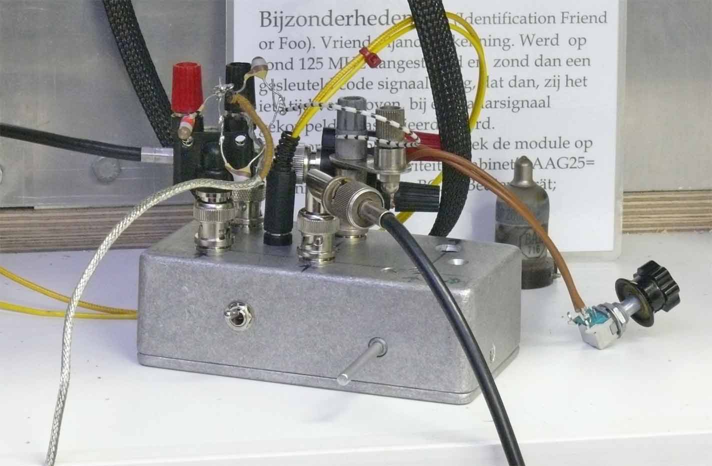
Our improved transistorised interface, of course, in some way still experimental; but no longer in use
![]()
It proved essential, to optimise the interactions between the FuG 25a I.F.F. transponder and the Gemse receiver part of the EGON ground system

In the meantime I also found space for setup the Philips synthesiser type PM5193, set at: 500.167 Hz. Below the R&S SMS generator which is set at 124.0000 MHz

It is quite obvious, that instrumentation improved as well. Step by step improving our according block-schematic; as did understanding
![]()
FuG 25a I.F.F. transponder is operating (covers removed)

Still our Nachtfee console isn't yet ready for its final set-up

A photo of the kind of the three-phase - phase-shifting devices; actually these had been designed as to be used as selsyn repeater (Drehfeldgeber)
But in Nachtfee being employed as to operate as a: sine-wave phase-shifter (0 - 360°).

Just before summertime 2012, we have moved from the rear hall towards the entrance of the main venue.
The left-hand sidelight above the compass indicates that the thermostatic quartz-oven is been powered.
On 3 September 2012 the next photo has been taken.

This is since our way of displaying the hypothetical aircraft system
It has to be noticed, though, that the complexity of setup increased considerably since.

Just opposite the simulated aircraft system is now the simulated Nachtfee ground system. Below the Nachtfee unit the R&S HF generator which provides the 124 MHz signal. On top of it the Philips LF synthesiser PM5190X, which has to provide the simulated EGON signal (PRF = 500 Hz); also being "a thing to be done". Right of the R&S generator, the TTi pulse generator and on top of it a power supply (20 V). On the far right on top of the wooden frame: the GEMSE ground receiver code-name Gemse. Below it the Variac transformer, which main function is to separate the Nachtfee power-lines from our regular mains, preventing hazardous situations. It allows also the reduction of the our current European power-line voltage of say 235-240 V; whereas Nachtfee should be fed with 220 V (also separately the quartz thermostatic oven)

Followed by one of our experiments, finding out what is the best way creating a circular, albeit, hypothetical, aircraft order-receiving display

This photo is, maybe, better providing the status of late 2012 instrumentation setup

Albeit improving, but not ready yet; tests undertaken around the Nachtfee instrumentation setup
Left-hand down the R&S SMS generator set @ 124 MHz, on top the PM 5190 generator; since used as EGON pulse-signal substitute.
On the left-hand front-leg mounted with binders our transmitter substitute, but functional @ 124 MHz. Quartz channel 6 (502 Hz PRF) being selected for this occasion.

System layout becoming increasingly complex
For better understanding - we would like to invite you to join our 25 November 2017 Seminar

Watching the increasing complexity of signals provided onto test-connector pin 9
Some of the signals might originate from transmitter-signal feedback onto the receiver channel input. Noticing that we, in contrast, don't possess the metal screen-off of an aircraft fuselage. The transmitter signal @ 156 MHz residue is found at the receiver input @ 124 MHz as well. In German practice - this might have performed better - as the antenna-matching-filter will better separate signals.

Viewing more in detail our mounted transmitter substitute
Please notice: the PM 5190 being set at the EGON substitute PRF of 500 Hz.
Simple - but effective.
E stands for EGON signal-pulse
N for Nachtfee order or command pulse
HF does not need an explanation

Another example of combined Nachtfee order and hypothetical EGON (on top our new PM 5193V synthesiser)
Please notice, generator currently operating at: 506.0307 Hz! (EGON operated regularly @ 500 Hz PRF)
Conveyed order just a few degrees passed north.
This synthesiser allows below 1000 Hz a setting of 0.0001 Hz resolution! In the early experiments an exciting feature was that also +/- deviation steps of 0.0001 Hz could be programmed and operated - up and down continuously; as to respond upon Nachtfee frequency-and-phase drifts.
This hypothetical setup constitutes our aircraft display, albeit not radial deflected like LB2, but Z-modulated.
Another example of a, hypothetical, Nachtfee due north signal combined (sharing) with EGON signal, but not jamming one another.
During the course of early 2013 it became apparent that the transistorised interfaces did not perform as expected.
Therefore it was decided to start designing an improved one operating valves.
My aim being employing valves in a way as the state of knowledge would have allowed in wartime days; but not pretending originality.
First building on the bases of RV 12P2000 weren't quite successful.

Then I considered starting to use LV 1 valves, which are possessing a 'high mutual conductance' (S = 9 mA/V)
It proved, however, that for optimal performance it was necessary to operate 3 valves. It has to be noticed, that the input signal originating from the hypothetical aircraft display unit, is sinusoidal and therefore signal must be distorted first as to get sharp edged pulses; valves possessing high mutual conductance are favourable.

Shown a nearly finished interface
The RV 12P2000 valve in the background was meant for blanking the 'hypothetical' scope trace at a certain vector, but have not yet included in our current concept.

And sharp the edges indeed are
However, I have decided to implement a second equally built interface

Our current setup
Albeit, that both designs are nearly equal, being matched particularly in regard to their input capacitances, it became possible to adapt both in/outputs in such a way, that no serious interference occurs due to the fact that at the video interface input both the test pin 9 signal is available; as well as onto this same point also the display-defection-timing-reference being supplied.
The only disturbing signal is the spot a few degrees passed 0°.
The RV 12P2000 could have been brought to function, but has not yet been implemented.

This is the described way both interfaces being employed currently
YouTube films
Film 97: Overlooking the new Nachtfee setup of our simulated aircraft system. On the left-hand side we see the FuG25a transponder down in the centre the newly designed interfaces this time fully controlled by valves. It has proved, that its circuitry can cope far better with the signals than does a transistorised system. Especially in respect to coping with HF signals. The interfaces are far less sensible to spurious signals like noise and that like. Which always are apparent in real environment. We built two interface modules, which electrically are equal, the only difference being their in- and output capacitances. It has proved that what ever signal wave-form is supplied very sharp pulses will coming out of it. (00097)
Film 98: Looking at our FuG25a set up, the control box (BG25a) at the right-hand side is indicating that transmission is being pulsed. This indicator indicates that real HF is apparent. (00098)
Film 99: Viewing more in detail the simulated aircraft system with on top of it the sine-wave TB synthesiser PM 5193V. Operating currently at 506.0312 Hz. Over some hours operation of the entire Nachtfee system, the system has quasi found an equilibrium. Tiny phase difference will be noticed in the way that the 'order' or command spot (blip) will rotate clock or anti-clockwise. What is causing it is uncertain. We may expect, that all variable factors are causing it. The PM 5193V internal time base - the internal Nachtfee time base and likely the non-linear warming up of the Phase goniometer controlled at the Nachtfee ground console panel. In the early days of the Nachtfee project, it was already encountered that when the goniometer rotor, thus its search coil, vector was changed that it took awhile before a new equilibrium is reached. Please bear in mind, that the 'Phase' control is an essential control, as it has to align the correct (quasi synchronising) vector of both the original Nachtfee order and what is being shown at the aircraft display screen. The continuous changing factor of distance is forcing its application! (00099)
Film 101: Showing the combined signals of Nachtfee 'order' or command as well as the EGON like signal. EGON was the secondary radar, which was being operated in a special way as it was acting as a regular I.F.F. signal, but its response was also used for measuring distance. The EGON signals looked like normal radar signals and used the Freya 500 Hz PRF. Whereas, our Nachtfee currently operates at a PRF of 506.0312 Hz. The 6 Hz difference looks small but these signals do not cause misinterpretations, as one is coherent and the EGON signal is not. (00101)
Film 103: Viewing the two newly designed interfaces. The left-hand one is being fed from the FuG25a test pin 9 output as well as from the right-hand module which is being fed from the time-base synthesiser PM 5193V; its output being fed onto both the left-hand side signal input but this signal is also galvanic linked onto the FuG25a test pin 9. Thus signal flowing both ways. The left-hand interface coping thus with the Nachtfee ground signal as well as the time-base reference or TB pulses. Its output is being fed onto the Z-channel of the oscilloscope. (00103)
These YouTube films with accompanied text have been copied from the to the valve controlled interface project page: Nachtfee New Thoughts Accomplished
Time has come to discuss our, albeit hypothetical, most recent system concept.

Let us clockwise follow the signal flow
The FuG 25a antenna receiving signals from the Freya-EGON station including the Nachtfee guest signals
The receiver output provided at test pin 9
One part continuing their path towards the I.F.F. coding or recognition module thereafter fed onto the FuG 25a transmitter and sending onto the Freya-EGON ground station
Intercepted by the Gemse receiver
Its video output split onto the EGON rig and the other part onto the Nachtfee input stage
The yellow line constituting the Nachtfee order or command signal path meant to be convey onto the aircraft system
The signal procession doesn't need further explanation, I suppose
The rest is quite self explaining
Chapter 4
On 28 July 2017
I would like to follow our rubidium-standard experiments on the lines of what is recorded on our website.
Albeit, that a selection has been made.
The implementation of a Rubidium Standard
Robert Langenhuysen (PA0RYL) brought up the idea of obtaining an Rb standard module.
During the annual OTC meeting held early April 2015, I could obtain a checked module; luckily a good one. Of course originating from mobile systems and employed for an estimated decade.
In first instance, I felt a bit hampered using it, as I was instructed particularly that great care in respect to its cooling must be given.

The accompanied product sheet was a rather promising starting point

Peter Kievits, a good friend of Marc Simons (Foundation Board Member), managed to built, with some basic support of Marc, a circuit with which basically provides two signals: 15,000 Hz and 500 Hz, both of sine-wave signature
My aims: sine-waves:
10 MHz at elevated signal level
15,000 Hz and 500 Hz
My choice, I would like to built it upon a chassis with the least possible mechanical preparations.
Like have been done before, so-called AMROH Uniframes proved again to be a good choice.
In this case, utilising a double frame.

An example of the emitter-follower coupling stages
Cooling is essential, as the Rubidium gas container needs for operation a quite high temperature.

In previous days, heated cathodes were implemented, but in our days an external heating element is providing sufficient heated gas, but the electronics is also integrated within this quite compact module
Therefore we need extra effective cooling.
Peter Eijlander very kindly gave me a cooling body once part of an old PC power-supply.
It does it's job more than perfect!

Another vision, showing what our Rb-standard is about
The small circuits in front constitute emitter-followers

After about 10 minutes, the red LED extinguished and the green LED takes over, signalling that Rb-locking is apparent
The SMD LEDs indicating certain state of logic.
My periphery is engaging quite straight forward techniques.
I hope that you can appreciate the Uniframe application; leaving enough room for changing thoughts.
Maybe the following measurements provide an idea how the various temperatures being distributed
On 25 December 2015: Staring temperature 18.4 - 19.4 ° C @ 11.53
Brief report on temperatures during 30 minutes of operation:
Rb- body (housing) temperature time after locking (green LED operating): 42.6°C @ 11.59 47.8°C @ 12.10 47.2°C @ 12.13
Cooling ribbon (block): start 21.8°C 26.8°C @ 12.15 23.4°C @ 12.23
Cu, top mounting strip: 23.4°C @ 12.12 22.6°C @ 12.27
It is apparent, that sufficient cooling is crucial and well maintained so far.
On 28/29 December 2015
I continued experiments started yesterday.
My first aim, to switch on Nachtfee again after a rather long dormant period for over more than a year.
Switching-on quartz channel 5 which should provide 500 Hz.
The output signal was being fed onto one scope channel, the other channel being fed from the Rb-standard. It was noticeable, that channel 5 did not provide exactly 500 Hz.
Our oscilloscope possesses a provision where channel 2 can operate in a X-Y mode together with channel 1.
It was also noticed, that the phase difference tended to slow. The quartz-oven warming up took just over 45 minutes. But still no equilibrium found.
My experiments on Saturday 26 December had shown that the PM5193 synthesiser was against the Rb-standard rather stable.
I therefore used the PM 5193 signal instead of the Rb signal.
Finally a kind of stabilisation was reached at a frequency of 499,9772 Hz. This synthesiser cannot make smaller steps than 0.0001 Hz.

Starting up the Nachtfee console again after a quite long dormant period

Quite a relieve, all functions again correctly.
On 29/30 December 2015
The next major step was taken.
Adapting a quartz-channel section of Nachtfee and finding a way as to inject the 15000 Hz Rb signal onto a faulty quartz channel; for practical reason I choose Q 1

First the front panel of the quartz section had to be removed again
Knobs have been removed and the panel waiting for to be un-screwed.

The 10 quartz modules are almost equal, be it, that minor adaptation had been individually accomplished as to compensate for the difference in quartz Q-factors and their according parameters
Quartz channel 5 operating 500 Hz PRF.
I choose (defect) quartz channel 1 on the most upper left-hand side.
I couldn't sleep well this night and weighted the pros and cons of the most simple and effective way of linking the Rb signal onto an oscillator circuit; and decided that G1 of the oscillator valve (RV12P2000) is the most logical point to start with (experimentally).

In late 2011 I drew a first sketch of the oscillator circuitry, without knowing yet how it actually did work; only considering the wires and components (a proper drawn schematic used in Chapter 2)
It is quite clear that this oscillator type operated a quartz crystal in series-resonance mode. When the oscillator fails generating a signal and the rest of the components are in good order, the quartz itself must be defect. I therefore injected straight away the Rb 15000 Hz output signal via two open twisted-pair of wires onto G1 of the RV12P2000. Even the negative feedback potentiometer did influence the 'output amplitude' a bit; as may be expected. However, the according quartz ➀ still being wired onto, but does not function.
An open query still was, does the existing 15000 Hz signal output provide enough signal level?
Yes, luckily, it does!
Hence, my estimation of a reasonable signal-level does work. As to reach this signal level, I choose, for practical reason, the application of an emitter resistor of 100 Ω instead of the usual 50 Ω resistor.
Maybe not the most maximum signal amplitude, but apparently the first (regenerative) divider stage does 'lock-on-to-it'
On top of the Nachtfee console the newly introduced experimental Rb-frequency standard.
What an amazing moment waiting for so long.
My next move, was taking the Nachtfee signal output and feeding it onto one of the Lissajous channels, the second one originate from the 500 Hz signal output of our new experimental Rb unit on top of the Nachtfee apparatus.

A schematic explanation how it works
Most of you will understand what it all is about.
The Rb-module is the common signal source - for both 15000 Hz as well as 500 Hz are (strictly) derived from the same signal source, and therefore will behave in coherence.
By this means, Nachtfee's internal 'components drift' comes to light;
their overall figures are really very minor!

The two Lissajous painting signals are coherent to one another as both originate from the same Rb-signal source

The difference only:- I activated the Freya-Polwender switch, which only interchanges the two Nachtfee output wires!
Only when signals involved are coherent to one another the 180° phase-shift can be observed.
On 30 December 2015 + 1 January 2016
I went to the museum again and did bring the entire Nachtfee system in an operational mode again.
I was relieved that all worked well. Always bearing in mind, that the Nachtfee ground console is older than 70 years.

The simulated aircraft system starts operating again
This time is it possible to watch an 'Order' signal that stays stationary at a single arc (180°).
This phenomenon I have never encountered before. The implementation of a Rb-controlled signal source is clearly making the difference.

The Nachtfee ground console is functioning well, but is now controlled from a Rb-frequency standard providing after division 15000 Hz as well as 500 Hz sine wave signals
For it quartz channel Q 1 being used as an interface, directly fed from the 15000 Hz Rb-controlled signal. (pink wires left of the Nachtfee apparatus). Why did I take open or twisted wires instead of a screened cable? Simple, because I wasn't sure yet whether the coaxial cable would not act as a capacitive load and thus reducing the available signal amplitude. The Rb-module is using an emitter-follower of 100 Ω. All works well, albeit, that the signal level output of the Q 1 stage is not very high, but apparently sufficient.
Another, practical reason, these wires do fit better passing through the space left onto channel module ➀.

Amazing is the constancy of the 'Order' or Command spot (blip)
That the circle isn't painted fully is due to our camera exposure processing. The dots originate from the also transmitted simulated EGON signal, which in this case has been chosen at 504 Hz; because the Rb-standard/divider provides 15000 Hz exactly. In normal operation - the situation should have been the other way around:- EGON sending pulses having a PRF of 500 Hz (Freya and that like system PRF) and Nachtfee therefore had to use Q channels other than Q 5 (after division its PRF = 500 Hz). As a consequence of operating 504 Hz - the difference is 504 - 500 = 4 Hz. Hence, the EGON blips rotates four times per second faster than does the Nachtfee blip. Would instead EGON having a PRF of 502 Hz the blip would rotate 2 cycles per second faster than the Nachtfee signal.
This could mean that my earlier estimation being valid; I calculated before that the Nachtfee system could have worked stable when the time-base signals would have had a stability in the order of about or better than 10-8.

Notice that the order or command pointer is actually set at due south (Pauke) and the LB2 due south blip is correctly repeating; but via the entire system loop - ground - simulated aircraft - ground Gemse Rx onto Nachtfee signal input
The pulse at, say, 8 minutes passed the hour is constituting the aircraft timing reference pulse, adjusted according to what has been proved, in our situation, the correct vector (timing) preset.

The HRP2/100/1,5A control screen
Both the upper and downwards facing central pulse, should be brought in line, as to guarantee that 'Range offset' being adjust appropriately
In my perception a most smart solution: aligning a signal against the display time-base-delay adjustment.
Film 0215: Viewing the simulated aircraft display operating with a Nachtfee system. The Nachtfee being now not quartz frequency controlled though being driven from a Rubidium (Rb) signal standard. Please notice that since the Nachtfee order signal stays quite fixed at given ground 'Order' signal. Very amazing, that with the help of an atomic standard it behaves is should expected; but never did!
Film 0216: Viewing now the Nachtfee ground console its time time-base frequency being derived from a Rb signal source. All works now as what should have done originally, though, likely never reached! The blips at about 8 minutes past the hours on the small CRT is representing the pre-setting of the Time-base (TB) originating from the actual stage of the time-base phase inside the aircraft. Only by this means can be guaranteed that the ground signal arrives at the correct instant on the aircraft display. On top of the Nachtfee console we note the experimental Rb-frequency standard. Nachtfee time-base signal now directly derived from the Rb frequency standard at least providing a stability of 10-10.

Basic system block diagram
Our PM 5193V synthesiser is providing a system stability at 500 Hz stable enough for application.
By the way, it was found, that the PM 5193V set at 15,000 Hz possesses less stability then at 500 Hz; clearly a matter of dividing factor.
The received order spot drifts in time, but being far less than would have been caused by an aircraft flying with an airspeed of, say, 400 km/h

The 'order' or Command spot visible just at due north (that the spots do not cover the entire circle perimeter is due to the camera exposure processing)
These lighted dots originate from the simulated EGON signal which being also transmitted.
Currently we obtained a brand new device, but of the same manufacturer, albeit, with another name on its attached label.

In front the older Rb module, mounted is the new LPFRS version 01 module
I had expected that this product was made somewhere in Asia, but it apparently is a genuine Swiss product; originating from their "time centre town" Neufchâtel.
I must also admit, that I have a penchant for precision technology; when available.
Deo volente, this is the closure of our intriguing survey
By Arthur O. Bauer
![]()