
R-78/APS 15A
more or less equal to the AN/APS 15 apparatus
Webpage initiated on 4 December 2014
Status: 16 December 2014
In 1943, the Germans captured such an exceptional and revolutionary radar apparatus about the (small) Dutch village of Meddo, in the eastern part of the Netherlands, near to Winterswijk and the Dutch/German boarder. According a recent e-mail it crashed on: vrijdag 4 februari 1944 (Friday 4th February) *
In those wartime days, it was German practice to call captured enemy equipment after the place where it once was found.
The British H2S system got code-name
Rotterdam Gerät (= apparatus), because it was discovered in a crashed British
Sterling bomber on 3rd February 1943, near Hardinxveld-Giesendam
. should be:
Hendrik-Ido-Ambacht *
Because this
village was quite near to Rotterdam it got the latter cover-name.
Similarly was done with the capture of an improved version of the British H2S set, which was found near Wiesbaden.
* We received on 9 December 2014 some e-mail corrections from a military museum near to Winterwijk
On the web I discovered this photo
It was mentioned that it equals British H2X
Therefore, we may link the H2X system onto this webpage as well.
In my perception, I am not entirely convinced that there might not have existed another kind of H2X system too.
Nevertheless, the sophisticated American version might have prevailed.
However:
As to counter their technical- and theoretical backlog, they established within two-and-a-half weeks, after their first encounter, a committee provided with exceptional wide-ranging powers. Without a great shock, like the discovery of the British H2S remains, such a Committee never would have been engendered! This Committee was called: Arbeitsgemeinschaft Rotterdam, abridged AGR. Their minutes of meeting are completely accessible on our website (≈ 525 pages), when you activate the latter hyperlink. For the first time in that era, a venture between: Industry - Science - and Military institutions were all doing the best they could to solve the many problems encountered; and many there were!!
The Germans were rather impressed by the state of US radar technology involved (1943).
The APS-15 apparatus used 3-cm techniques. This latter technique was regarded by them being the most favourable!
But, they were just trying to bridge their backlog in 10 cm radar technology; therefore the entire new technique simply was a 'bridge too far'.
To what I know, three German 3 cm prototypes have been built and tested. Not based upon APS-15 principles, but using common H2S/Berlin techniques; only the TX and RX being adapted for 3.2 cm. They therefore developed especially the LD 20 reflex-klystron, nevertheless, without doubt, based upon US 2K25 (723A?) like techniques. Whether they used wave-guides I don't know. According to Fritz Trenkle, they used coaxial techniques instead. However, from other sources we know, the Germans possessed samples (copies) of the 725A magnetron. They even might have manufactured some of these themselves. Consider, for instance, the CIOS III-1 report on the Philips works in Eindhoven of September 1944. There is dealt with a magnetron cathode of 2 mm diameter, the CV 64/LMS 10 certainly had a quite bigger cathode. Considering the further down explained mechanical dimensions of the 725A magnetron, these figures are far more pointing into that direction - than was employed in British H2S related techniques. We should also not forget, that what is being referred onto was from an aural recollection. However, there cannot be any doubt, that the (German) one talking about these parameters, must have known what it is about (telling Philips people certainly was illegal according § 88, as it concerned one of Germany's highest secrets)! In contrast, Philips in those days did not have any knowledge of these modern techniques! Philips was regarded being an alien company and was not trusted. In the first years of the war, also the C. Lorenz A.G. company was considered this way (defacto owned by I.T.& T., also known as I.T.T., since May 1930). After the war Philips had to start entirely from scratch. (inventing the wheel again)
However, the German industry was struggling too much as to be able to cope with all the new demands and always facing increasing problems (and shortages).
Just over a week ago, I received a letter in which a friend of mine informed me - that in the Dutch town of Goes an old amateur is trying to clear his attic. After a telephone call I decided to take a look.
I discovered, among many other devices, an APS 15A radar PPI accompanied by a modulator, two transmitters fit with 725A magnetrons and an antenna scanner.
Bearing in mind that the Germans called it once Meddo Gerät, I decided to obtain it, and creating a new exhibition subject.
May be to be called: Captured Enemy Radar Equipment (CERE); as the Americans could have designated it.
It definitely is not our aim to reconstruct it, and bringing it into a full working order again, but I would like to show what superior radar techniques the Americans possessed.
Considering all we obtained, it might be possible to let it operate again, but education is for this occasion our aim.

Viewing a picture of the German technical Meddo investigation report, done by Telefunken
Please consider the following hyperlink, as to view what the Germans wrote about it, in 1944.
Our equipment is about equal in respect to the above described PPI unit. The modulator, however, I guess genuine, but is of a different type than what the Germans recovered from a crashed US B-17 bomber aircraft, in 1943.*
Also the design of the RX-TX differs, but both units we obtained are using 725A magnetrons and a 2K25 reflex-klystron as L.O. Although, according the German wartime Meddo report, it used then a 723A (reflex?) klystron type acting as local oscillator (L.O.).
* In spring 1944, they captured a fully operational B-17 bomber aircraft, which had made, for whatever reason, a landing near to Calais. Afterwards, this aircraft was flown from the Werneuchen site NE of Berlin. Of course, fit with German designations. From this site photos do exist where they investigate the APS-15 radar system.

It is apparent, that what we obtained last Tuesday equals in most respect the German wartime capture, shown in the previous picture

R-78/APS-15A type number plate
I have just given my old friend Jan ten Have a quick phone call, asking him what he can make from the information provided.
He later replied - that R-78 points to a naval application. He also stated, that the US Air Force in Europe had a naval section too. The stamped-in 'anchor' symbol down in the centre, might underline his judgement.
Let us consider first what arrived in our premises, last Tuesday 2 December 2014
Previously, we have removed the cases.

Considering the connector on the left-hand side of the IF module, the previous amateur/owner might once have replaced it. Or is it a genuine one?
What should also be noticed, the previous owner once replaced the power-supply-transformer as to adapted onto 220 V 50 Hz mains instead.
Quite understandable, as according to the type-plate it should have been fed from a 115 V 400 Hz up to 2400 Hz supply-voltage. In avionics, or other environment, rotary converters (later maybe transistorised) were employed. These are rather clumsy to maintain in living- or hobby-room environment.
Please do understand, that he got it once fully working!

The rather heavy 220 V 50 Hz transformer is clearly visible

This transmitter-receiver unit might have been modified by the previous owner, but likely, some originally belonged to the genuine application. The chassis might have once belonged to an equal transmitter type
The IF strip on the left-hand side might originate from a later date.

Viewing the 725A type magnetron with its quite bulky and heavy magnet
The grey box on the far right-hand side is the filament transformer, or at least acting as a separator. Don't forget, the filament is also directly (galvanic) connected with the cathode. Anode being at ground potential, the cathode should be operated at pulses up to - 15 kV. This becomes more critical as height (altitude) increases. Therefore, US equipment often was kept inside a tubular container, likely at some nitrogen pressure. Sound, but rather demanding.
I know from experience, when I was once engaged in radar maintenance, that high power radar systems kept some of the wave-guides under nitrogen pressure, as to prevent arcing. Considering 3 cm wave-guides, their internal dimension are relatively small.
One may wonder where the magnetron actually is hidden.
The magnetron is just in between the middle of the two tapering curved magnetic pole-plates. But, at 3.2 cm internal dimensions are small. The diameter of the inner-anode-block is only: 0.259 cm (ra), the cathode radius being 0.1298 cm (rk), height of the anode-block being 0.635 cm (6.35 mm); the latter dimension is also determining the occupied space between the two square plates, of course, the strength of their copper walls should be considered too. Nevertheless, truly small dimensions. I do not know, what the actual outside diameter of this magnetron is.
The cathode radius of 0.1298 cm (not yet 1.3 mm) consists of an internal filament as well as an outside cathode capable of providing pulse-currents up to 10 à 12 Amps!
An important parameter of magnetron design, is the ratio between the cathode- and anode- radii (rk/ra).
On 9 December 2014
Some details on the way the 725A magnetron being mounted.

We are viewing in detail the 725A magnetron being mounted in between the two magnetic poles
It is clearly visible that there exists a gap between one of the magnetic poles and the 725A magnetron body
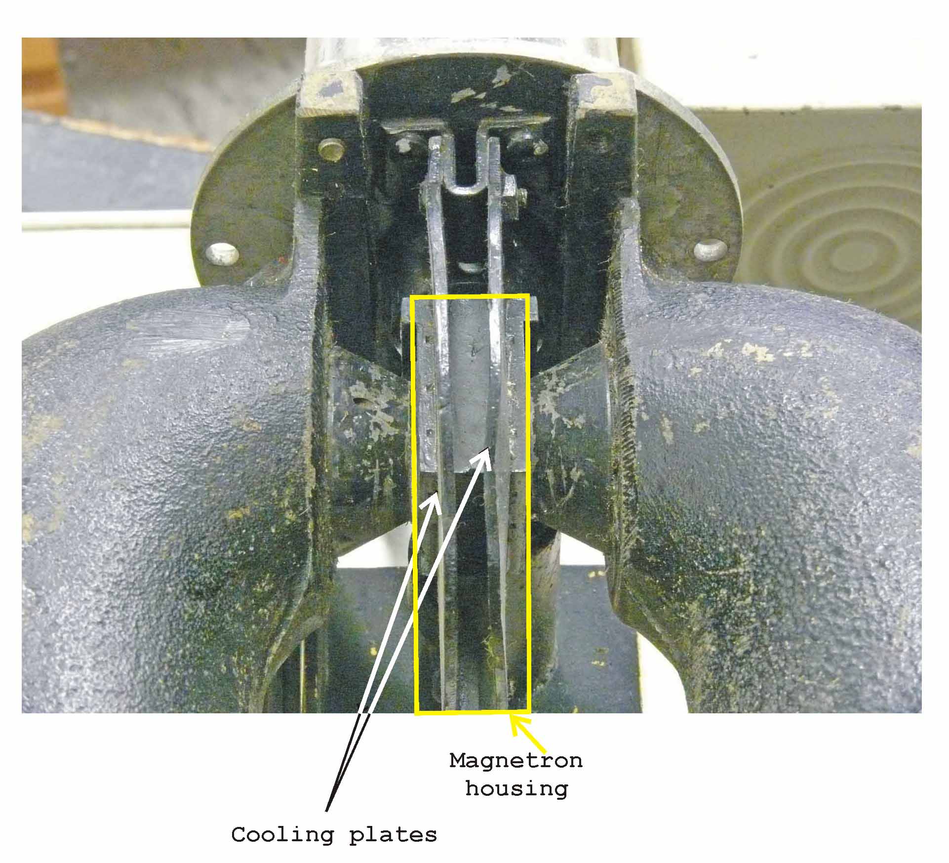
For this occasion we have marked the cooling fans of the 725A magnetron (white arrows) as well as the the actual 725A magnetron body (housing) (Yellow)
The disk marking the top of this photo is belonging to filament centring and insulation dome; quite necessary as at the filament is fed also with pulses of maximally - 15 kV against ground (chassis and magnet).

Showing the way the HF power being linked between the 725A magnetron output and the 3 cm waveguide system
The cooling fans are also fixed mechanically onto the HF output connection of the 725A magnetron.

Curiously, viewing the same JAN 725A magnetron, now providing a different manufacturer. In previous days this designation was quite commonly found and stands for 'Joint-Army-Navy'
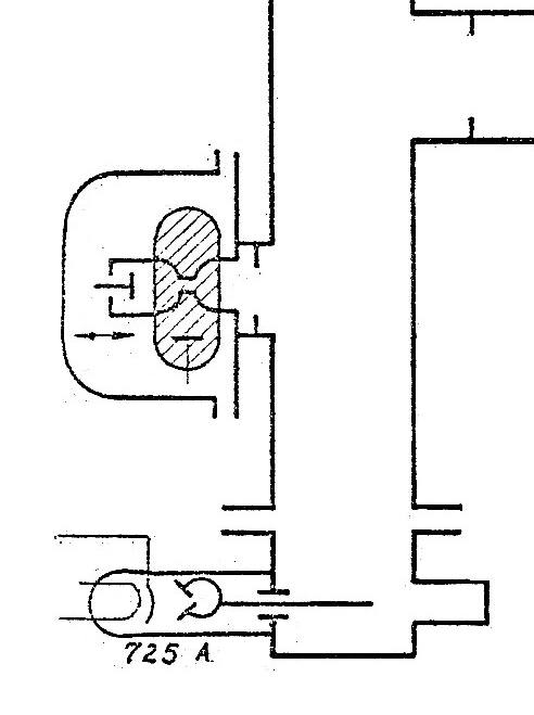
This schematic is derived from the German Meddo Bericht of 1944 (previously mentioned), it might well showing the way the HF output of the 725A magnetron is connected onto the waveguide system
Let us continue again with what has been accomplished previously

The 2K25 reflex-klystron (hidden within the shielding box) is a well known device and was used for quite a long period in many applications

Viewing the front section of the antenna scanner
Allowing a horizontal as well as a vertical scan.

Viewing the rear of the antenna scanner

Please notice the micro-switch, likely used for providing a 'north-marker' pulse- or reference
Before we will put the devices on display, let us first consider the second transmitter we got.

Again viewing a 725A magnetron, but now approaching it from the filament feeding side
The way the wave-guide is connected onto the magnetron, shows how much the magnetron output is adapted onto the wave-guide arrangement.
This transmitter module might also originate from a later date.
But this is what we got.
I have not yet been able to find-out what constitute the T/R switching (separating) device.

On the left-hand side we see the 2K25 reflex-klystron valve
On the right probably the IF stage.
Whether it is implying a STALO is not known to me.
We decided to clear the 'Radione R3 - RS20M' station shelf, which has been on displayed since late 2008.
Now we start showing aspects of the APS 15 system

From left to right: the modulator - one of the transmitters - and - the R-78/APS15A PPI

The transmitter module being placed in the centre of the shelf

According this information, our guy from Goes measured in May 1970, that the 725A magnetron operated at: 9395 MHz
The information down, apparently having a different handwriting, provides: 9586,5 MHz

Luckily we obtained most of the cabling too
As to show what this system is about, we left the cases (boxes) off.

On top of the Rudolf DMG3a apparatus, we have placed the antenna scanner including the genuine mounting structure; allowing the interconnection between antenna scanner and the PPI unit
On the far right-hand side, just visible, the empty case of the APS 15A PPI apparatus.

Viewing it from a different perspective
No doubt the pedestal is genuine.
Our next move might be combining the H2S transmitter, equalling the one the Germans captured on 3rd February 1943 near to Rotterdam. Maybe implementing (combining) also the German SG 224 radar PPI display (FuG 224 Berlin system); which technique was based on the captured Rotterdam apparatus.
For it, we first have to decide where and how this should be accomplished.
For those who want to contact us, don't hesitate:
![]()
Please type in what you read
By Arthur O. Bauer
![]()