
TFb 2
Survey
Getting our wartime mobile carrier-telephony system TFb2 in a working order again.
Start of our Survey on 25 February 2017
Status: 10 June 2017
Approach B + C + D + E + F + G +H
+ K
The left-hand side our TFb2 apparatus under investigation

We would like to see how it looks on the rear side

Secondly, how it looks behind the front panel
We are looking at a typical Siemens way of telephony module construction (Bauweise)

From its wiring we can see that it concerns quite a complex schematic
For those interested in a better printable schematic, click at it
It has to be noticed though, that this schematic shows only the so-called: two-wire- in and two-wire- out situation. Whilst it also possesses the options for, either 2 - in, 4 - out or inverse 4 - in and 4 - out.
TFb2 is operating at a carrier frequency of 11 kHz.
Later we, Deo volente, will go deeper in to the technical aspects.

Viewing at it from a different perspective

After having switched on the 12 V supply, buzzing sound started and the control meter responded by erratically going a little bit up and down, but never reaching its full voltage, however, after a few seconds all stopped suddenly

My first thoughts went, the vibrator pack is striking

My second step was dismantling this device
But contacts weren't looking oxidised or being jammed

The concerning HT power module more closely
Before starting with dismantling it, I inserted in first the open vibrator pack again, so that I can touch the contact fingers
Then I measured the resistance between ground and +A, where a resistance existed of, say 41 Ω. A far too low value, and apparently overloading the power pack inside.
I also became aware, that the battery + is connected onto (system) ground, whereas the - pole being handled as the actual battery supply.

After removing 4 heavy screws (not meant ones keeping the power pack together), of which I have no idea yet how these being fit. It was found, that an electrolytic capacitor being apparently defect
But, inside the power pack, the construction is very crampy built and lacking room for by-passing another electrolytic capacitor. What also was found, is, that the components being numbered but not on the schematics at hand. I therefore decided, to disconnect the failing component on one side, and adding at the output contact, an additional 22 µF 450 V capacitor. At least, without load it should run smoothly.

Seemingly the power module being mounted insulated within the (main) frame. Consequently ground is determined at a single point. From the electrical point of view, this has an advantage

Closing for today, we notice:
Rel bk 61a
Rel SK XX D 3/3b
Ausg. III
Date: 1.8.44
However, even operated without outside load, the voltage doesn't exceed 89 V. Hence, we first should consider this device first.
(B)
On 11 March 2017
Although, in the meantime some small experiments have taken place, these have been in average unsuccessful.
Yesterday, I took time to reapproach the annoying repeating defects again. First it was found that with increasing test duration the vibrator tended to stop and sometimes did strike entirely.

Visual inspection shows that this device must have been quite warm, because tar is being pressed outwards
Such phenomenon is quite common when dealing with tar-composed capacitors. What actually happens, is, that tar shrinks and the dielectric wax is hygroscopic and therefore ultimately constituting an inferior dielectric and insulator, when being confronted with high tensions; such capacitor warms itself up and finally breaking down.

Every experimental step was followed by a next nuisance
Although, measuring it on our General Radio Bridge type 1602 all seemingly was OK. Low loss and correct capacitance.
Please notice the wartime Siemens specs: - 40° to + 70° C
The only strange fact is its apparent maximum voltage range given for 15 V pp, whilst it should operate at 12- 13 V dc continuously.
However, I replaced the device and, it might be that the overall performance became better.

The nuisance, the clamping provisions have each time to be pushed to the left-hand side, which isn't always easy
In the back, invisible to us, are rectangular kinds of screw-nuts. Its shape prevents its rotation, but it is time and again tricky to move them out of the way.

Left of the metal strips are kept the rectangular nuts

Now a range of parallel set of measurements being commenced
The meter in front showing the HT current loadwhich is, say, 10 mA.

The meter on the left, measures the 12 V current consumption of the entire Tfb2 apparatus, which is 0.62 A; the right one shows the power-pack HT of 221 V (loaded condition)

Viewing it from a different perspective

It was also found, that the overall performance enhanced, when a stabilised power supply parallel onto the existing (genuine) power supplied is added; which might be caused by instability of the genuine Siemens wartime stabilised power supply
Data:
11Rel.besch 510/04a Bl 2 v 4.11.42
A quick internet search didn't bring a match.
Is there someone around who can provide additional information on this quite mysterious circuit?
Our apparatus had been once modified in Denmark (before I swopped it in the early 1980s), where at least the selenium rectifiers had been replaced, mounted on a rectangular PCB, by a bridge of silicon rectifiers.
The series L/C parallel onto the transformer designated Tr, might be like a regular series tuned at 50 Hz; or should it be 100 Hz? The transformer device designated VD might constitute a transformer having an 'air-gap'.
All bits and pieces of information on this topic can be very helpful for our understanding of this type regulating loop-system.
This additional stabilised power supply works fine.
But I have been too many times too optimistic.
Let us see what the next confrontation might bring us!
(C)
On 23/25 March 2017
Time has come to test the power supply over a longer operational period; and it was also decided to access the Siemens 12 V magnetically stabilised power supply inside.

A new approach has been initiated
The the battery controlled Tfb2 (left-hand side) runs now rather stable, and we would like to look why initially the Tfb2 power supply fail operating appropriately.

Fabr.Nr. 363301
Bez. NA-Gerät für TFb
Zchg. Nr. 11 Rel.trgb. 17a
Spanng. 90 ...250 V
Baujahr 1942
What I never expected, this device indeed operates below 110 V perfectly!
However, when temperature of the internal components reached a certain level, it even operated more reliable when the mains was reduced to 110 V or beyond.
The voltage swing from 220 (230)V down to 110 V didn't change the loaded output voltage (12,90V), within the range we measured; hence > 0.01 V.

Not bad isn't it?

The 'variac' being set at an output voltage of 110 V
Even beyond, I guess 90 V or even less, it wasn't possible to deviate the 12.90 (12.89) volt.
I never expected this incredible stability figure!

On the left-hand side the device designated Tr. corresponds with the one in the schematic below, on the right the device VD is the 'air gap' transformer

The device in front, designated ED is the series resonance choke tuned at 50 Hz

As to make resonate at 50 Hz, the foregoing showed choke ED apparently in series with this 8 µF capacitor is doing the job
The quality after some 75 years past may be regarded 100%.
Why?
Because of its hermetically seal-off technique; a most outstanding technique widely used in German wartime apparatus; particularly were critical circumstance occur.
As to understand the foregoing description better, its schematic being reproduced again
The capacitor parallel onto the meter has a value of 3 µF. Maybe this quite large value have been implemented as to prevent for 'switching-on annoyances'.
YouTube films showing some aspects previously dealt with
Thinking it over again, we might explain the circuitry as follows:
The transformer designated VD provides at its secondary side a proportion of the supply voltage needed for the ultimate 12 V dc output.
But, the VD device might have been fitted with a 'core gap' causing a less efficient energy transformation.
Transformer designated Tr is being loaded with the series tuned circuitry consisting of choke ED in series with a 8 µF capacitor. A series tuned circuit constitutes a low impedance at its resonance frequency, which must be considered here being 50 Hz; and is acting more or less in an ohmic manner (we may not neglect the loss within the choke device ED). But such circuit will cause that current will flow through the second winding section of this transformer. But its current isn't dependant upon circuit load, but purely on its series tuned circuit parameters.
Transformer VD will cause more energy transfer loss with increasing load current; hence, providing a lower voltage portion (all together). Somewhere there must exist an equilibrium, but this is given by the various interacting circuit parameters.
Now an estimation, significant is the tuned ohmic circuit at 50 Hz, which will cause a more or less constant current flow through its series tuned circuitry. Normally, loading is dependant on the load provided, but in this case its behaviour is only its ohmic value, but a constant loading.
In an catalogue yesterday (6 April '17) provided by Florian Eibensteiner from Austria, it was quoted that also vector summations took place. But the devices handled within it were pure AC power supplies. I cannot judge the amount of phase-shifts encountered between the output of Tr and the VD devices.
I must admit, that my explanation might not be fully correct, please come forward and explain it on the hand of existing literature.
I must also
admit, that the swinging choke following the rectifier (Graetz) bridge, is
curious. I can remember, however, that such a device is provided with an air-gap
as well, it hasn't an
airgap causing - that with increasing current a decreasing self-inductance (core
saturation) will come into affect; as to compensate the normal (low-pass-filter)
voltage drop. Such a provision has to be designed for its particular task.
Interesting is to notice: that when there isn't a load existing at the output terminals, that the output voltage reached >> 20 V dc.
This is due to the lacking saturation effects caused within the VD and to a lesser extend by the swinging-choke loading the rectifier bridge.
Please, repeat reading this explanation, as to become more acquainted to the way this technique works.
I never expected that such a non-electronically controlled circuitry could operate so sound as does ours. Over an input swing between, say, 90 V and 230 V ac mains input.
On the other hand, when we started up this stabilised power supply first, I encountered a rather instable voltage output.
During operation in an opened condition the temperatures rose, over time, from room temperature, say 21° C up to:
55.4° C for the transformer core Tr; its windings became 47° C
32.8° C for the VD transformer core; windings about 32.8° C
42.3 for the ED core; whilst the winding temperature outside gave 44.4° C
The rest of the components, including the series capacitor of 8 µF as well as the parallel capacitor of 3 µF holds a temperature of 22.8° C
With increasing duration of operation, some slight increasing voltage deviations came to light. This could be cured fully by reducing the supply voltage down to 110 V ac. After a while, the voltage was being brought to 220 V; and all operated entirely stable again.
We might draw the conclusion, that the transformer and tuned choke circuit does cause this minor instability. Therefore we find at the front panel the rather unusual cooling grids.
The perforations are good visible and does make sense
(D)
On 6 April 2017
I proceeded with our Tfb2 (carrier-telephony) project.
First the second Tfb2 unit had to be taken out of its case, because apparently the anode supply voltage was far too low being 117 V.
It showed that blocking capacitors were having signs of blowing cases.
But a misfortune, some wires were broken off but where to connect these onto?
Maybe one point hasn't been cleared yet, but the filaments being supplied with about 12.6 V, as well as the HT is available.
In the meantime some time has been spend on getting at least two telephones operating appropriately. Problems have been encountered with the carbon microphones, for which a test facility is lacking. However, the two sets operating are performing perfectly well.
The Leclaché batteries being replaced by Duracells type D, within an appropriate battery holder . On the internet we could also purchase a good bargain of Industrial types.

The current test setup
After some gain adjustments all works remarkably sound.

Quite amazing that after say 73 years such a system can be operated again

It can be noticed that this set went into post war service again in 1948, and last revision had been commenced in 1953
According the text on the white plate it had been operated between Straubing and Deggendorf in Bavaria. This set constitutes post A, whilst our second set being operated in station B mode.
This set is being supplied by means of a provisional internal mains supply. A bit crude, but might do the job.

Viewing the speech signal on the carrier telephony interconnecting line.

Another speech example on the carrier interconnection

Hans Goulooze talking on the FT33

One of my tests
(E)
On 5 May 2017
Last month, before our trip to Germany, we did photograph the situation where we operate two field-telephone sets on either side of the carrier-telephony stations.

The set-up becomes a bit more complicated
Two field-telephones on either side of the 'line' operating a single pair of wires.
The carrier frequency is 11 kHz and the second channel considered a regular LF path.
Viewing it from a bit different perspective

The way the of interconnections
NF-Gespräch represents the low-frequency link.
TF-Gespräch is the telephone operating via carrier-frequency channel.
Fernleitung (the lowest connections) is the line via which means communications takes place.

Viewing the other end of the line which should both be equal interconnected
YouTube films demonstrating two differnt communication channels one carrier-telephony in SSB and the low frequency channel. Also showing talking A → B and B ← A one way USB and the other way in LSB (@ 11 kHz)
(F)
On 12/13-15 May 2017
A new approach has been undertaken, with the aim getting bells ringing (again) at the channel stations on either side of the TF-line, designated station A and B.
It has proved to be quite a challenge!
Partly because we do not possess adequate documentation, and had to accomplish it with the next shown schematic solely.

This schematic will be the nucleus of chapter F
Please click at it as to get it in PDF format

On the right-hand side of this module I measured the signal shown just below, however, on the left-hand pins I measured no signal at all

In the status of my understanding of this module shown left of arrow 'A' that the defect must be inside. Therefore I removed it from the frame and brought it to our LMK lab.
By the way, this signal is the one generated by means of the vibrator unit inside the module designated: Relaispolwender PW.

Module Rel NBv BF 1123, Rel bkb 114a, being removed
BF likely means: band-filter.

Leaving behind an empty compartment
By the way, the module left of it, will proof to be the LSB channel side-band-filter.
Please notice on the upper right-hand side, the post-war built-in mains power supply.

With the help of a simple tone generator, I connected a signal at the input terminals and watched the oscilloscope screen connected onto the output pins
The band-pass started at about 11.2 kHz and responded like the next drawn curve; briefly band-pass facilitated between, say, 11.2 and 13.4
I do not claim accuracy, as the HP tone generators being fit with a rather coarse dial. However, it proves at least that this module operates adequately; and it also was noticed that the input- and output level differed only slightly.
However, the consequence of this finding was, that my preliminary perception of this schematic was wrong, because the operated filter was the LSB filter type BF 1122 instead (below)!
I simply forgot to notice that in the setting operation switch (A or B) was just interchanging sidebands.
An important discovery for me was: that the input signal at the moment I did my measurements went through the opposite filter section, whilst both on the left-hand side being interconnected onto U 1443.
The next confusion arose, with measuring the signal at arrow point 'B'. A distorted square wave like signal was recorded but the 500 Hz bell-signal couldn't be noticed.
Why?
Because valve Rö 1 being operated in a kind of dual mode. It operates first as an oscillator at 11 kHz (Tfb2 carrier frequency), but also acts as an signal amplifier.
A quite strong, partly distorted, signal was noticed at arrow 'B' originates from the fact that the cold end of transformer Ü4 being wired onto two diodes in anti-phase. Hence acting in this configuration as a signal limiter; however also a positive signal feedback is closing the amplifier (oscillator) loop.

The scope probe connected onto a 0.1 µF capacitor and measuring at arrow point C

This kind of signal being measured at point C; albeit not exactly like this, but the situations are reflected in one of the following YouTube films
Encircled circuit descriptions
Arrow 'E' and related circle.
The ≈ 20 V 500 Hz sine wave signal is being generated by means of a vibrator* relay; its (sine) wave pattern has been noticed before. The two encircled (alternating) relays are generating the 25 Hz ring-tone-sequence by means of causing square wave signals. That both the 500 Hz generating circuit as well as the bell signal generator being combined might originate from the perspective of space-convenience.
* It operates so smoothly and hardly making sound, that I didn't notice its operational existence.
Let us focus our attention onto the circuitry inside module AG 1248.
The two tuned circuits within the circle is quite ingenious.
The upper parallel tuned circuit responds on longer lasting 500 Hz ring-tone signal. The lower series tuned circuit consisting of C29 in series with L8 is interrupting the voice channel (Sprachsperre); because a series tuned circuit constitutes a low resistance at just 500 Hz.
Gl7 constitutes, in my perception, a limiter circuit.
What after all might have caused our problems?
In succession of discoveries:
Arrow 'D' points at 12 dc. My way of approaching mystic problems of which I don't understand a circuit comprehensively, is, to view for apparent signs of information. My attention was attracted by noticing + and - 12 V (dc) (text printed on the pertinax terminal strip). However, our apparatus had been 'modified' in 1948 and 1953; at some moment an AC power supply was implemented (replacing the genuine build-in vibrator pack), but in a quite crude manner. A low voltage rectifier does exist, but without wiring and blocking provisions. Measurements showed that with a blocking capacitor and some circuit loading 17 V was provided. As to leave it this way, I took a separate power supply for 12 V first.
Also confusing, they interrupted the 12 V supply lines somewhere internally and did feed 12 V ac at the RV12P2000 filaments instead.
However, after this additional 12 V dc power supply I could send ringing signals (originating from a telephone inductor) to the other station (left-hand side of the table). But it proved impossible sending a comparable signal towards the on 230 V ac running rig.
Then I had to go through a fault-finding session described in this chapter (F).
A nuisance was caused by my own poor soldering the + wire of the 12V dc between the power supply and module AG 1248; simulating an additional fault.
It was discovered, that when I switched the transmission mode A → B in B → A that also some matters weren't responding equally. This apparently was caused by switching contacts oxidation (73 years old). Using contact spray and switching it multi times between setting A and B it started to respond more appropriately. Then, I re-soldered some cable contacts, and it started to respond at a certain stage as so desperately was awaited for.
All the foregoing procedures enhanced my circuit understanding, which I otherwise never would have gained.
What was quite confusing, was the fact that comparing signals (between both Tfb2 sets) measured at equal circuit-points showed sometimes quite different responses and voltage values. In my perception, likely (also) originating from the parameters of the diodes involved, which were of the Sirutor type, and originating before the post war semiconductor revolution; these devices responding, nevertheless, adequately.
On last Saturday, I took the chance making three video recordings, which quite well follow the line of developments.
YouTubes films:
Please have patience, as I had to accomplish it all myself without assistance. The circuits under investigation just being described in this chapter F.
(G)
On 19/20/22 May 2017
On the 19th a new nuisance occurred as some functions refused to operate again and several new approached have been undertaken; providing better understanding of this complex apparatus. Albeit, that still the test function refuses to operate. The fault could not yet be determined because I still do not understand the implications of the schematic in regard to pressing the Test knob.
It was encountered that the fault started to show up by the fact that sometimes, when starting up the Tfb2 system, that the test facility operates and sometimes it does not. Soon followed by a total malfunctioning of the Test signal facility.

This relay panel controls essential calling functions, like triggering bell signals on its own side or at the opposite station on the other end of the carrier-telephony line

The three foregoing relay and their interactions being explained, for, at least, what causes the system to start-up the bell signals
RR is being triggered by the inductor signal and consequently activating relay AR
BR is switching a range of relay contacts of which kI and/or KII is starting up the bell-signal-generator (500 HZ) but also disconnecting the Tf-Gerät (2 wire telephone) from the circuit loaded with the relay circuit RR. The 500 Hz bell signal will now be fed solely onto the outside terminals of the Tfb2 apparatus.

A nuisance was encounter by the finding out what causes malfunctioning of the control meter, apparently water damaged the moving coil system
A meter was found that experimentally to fulfil our requirements a bit; albeit that some reading clearly overloaded the instrument whilst the HT and 12 V indication showed inadequate readings (too low)
I decided therefore to approach the circuit in particular.

Pure by good fortune I approached C 1740 attached to Rö 1 circuit

After a mistake, where I disconnected the incorrect p3 instead of p2 and inserted a resistor of 470 Ω and meter reading was considered satisfactory.
My confusion arose after I discovered that there should be other C 1740 units involved too.

and

C 1740 interconnected onto Rö 2
In all three cases the p2 should be disconnected, albeit, that for the circuits to Rö 2 and Rö 3 a 1 kΩ resister should be implemented.

Rö 1 tested; meter reading about the centre reference

Rö 2 reference about the centre reference

Rö 3 just passing the centre reference line

W 1381 is the resistor module containing the resistor series R38 - R41 shown in the next schematic

R39 and R 41 had to be bypassed by two 47 kΩ resistors
R 39 had to bypassed between p3 and p4.
Next my attention should be dedicated to the malfunctioning Test facility. However, there is found a buzzer, which functions in the correct operating set when the Test knob being activated. The problem, I have not yet discovered where to trace it on the schematics.
(H)
On 25/29 May 2017
Some enormous progress has been made, on which we would like to report upon.

As to keep you in touch what it all is about, the general schematic has been reproduced again
We have reached a point where calling (inductor) signals can be conveyed into either directions, but the "Test" mode on our once modified set (right-hand setup) did refuse operating after a while.
The question arose why?
Then Florian Eibensteiner contacted me and quoted from the handbook put on the webpage.
Lieber Arthur,
im Abschnitt “V. Betriebs- und Pegelprüfung” der Datei “Tfb-Survey-F-Das Trägerfrequenzfergeraet.pdf” ist der Prüf-Vorgang beschrieben: es wird durch Verstimmen der Gabelschaltung (durch Anschaltung von L5 und C20 im Modul F 1352) und durch den Empfangsverstärker ein “Rückkopplungspfeifen” mit 500 Hz erzeugt. Diese 500 Hz bringen das Ruferkennungsrelais ER zum Ansprechen, das in weiterer Folge die Relais AR und BR schaltet und den Relaispolwechsler PW schnarren lässt. Erst bei neuen TFb 1-2 (gemeint ist “neue Serie”) ist ein Wecker (= Summer) eingebaut. Dein Schaltplan dürfte daher die “alte” Serie TFb 1-2 zeigen. Der Wecker müsste an den 20 Volt ~ (im Schaltplan blauer Pfeil und “E”) angeschlossen sein.
He pointed that in the "Test mode" the system was forced as to oscillate on 500 Hz. Albeit, that the components quoted differed considerable from our schematics, it, nevertheless, confirmed my preliminary suspicions. But still remains open: why doesn't it oscillate currently?

Let us first focus our attention on to the red encircled circuit switches
As to get this schematic in PDF please simply click on it
Red encircled A
It disconnects the receiver-channel-input (from the apparatus outside line), and interconnects the output signal of the transmitter (Sender) onto the receiving channel (Empfänger) input instead.
Red encircled C

Closer view at the circuit what happens with pushing the "Test" button 'Prüfen'
In normal operational mode the 'Prüf' switch short circuits the series tuned circuit arrangement consisting of L 5 and C 20. When the "Test" mode being activated the series resonance operates at 500 Hz ( = the bell-tone signal, Rufton) and is also detuning the hybrid circuit balance.*
The in/output-line balance against the line equivalent circuit on the left-hand side of the hybrid-transformer (Gabel or Fork) circuit; the circuit on the left-hand side constitutes a balance with the actual line equivalent (it should substitute it). Such provision is necessary as to separate the receiver- and transmitter (out- input) channels from one another. Optimal balance matching demands care as to prevent signal echoing or that like. Such provision was maintained standard in the cases where single line (two wires) telephone signals had to be linked onto a so-called four wire system; where separate receiver and transmitter amplifier chains being maintained.
* The relay contacts 'br II and br III' were triggered indirectly and separated the in-/output (2 wire) line from the hybrid (Gabel or fork) transformer.
By disturbing the hybrid circuit balance, the receiver output can now flow into the transmitting channel.
In the meantime relay contacts marked within D and E cancelled the influence of the ring modulator circuit (balance modulator). Not yet clear to me, whether the common carrier oscillator being detuned an additional 500 Hz as well.
Switch circuit covered within red encircled F feeds the transmitter channel output onto the receiving input via switch marked A again (instead onto the outside line provision). A (possible) oscillating loop is created, which can only be maintained at the series tuning frequency of 500 Hz, that is the series resonance frequency of L 5 and C 20.*
* Outside the series resonance the tuned series circuit constitutes a high impedance and, considering the low line impedances dealt with, which is not detuning the hybrid circuit balance, and the signal loop being interrupted to pass into the transmitter channel again.
We know that for a closed loop amplification (blue line) the theoretical condition being regarded "loop gain is 1".
Red encircled B
It measures the output level of the oscillating circuit; indicated at the test meter (when the test-selector-knob being accordingly set).
After having checked all switching contacts and according wiring circuits still no signs of oscillation was observed.
For an amplifying loop (in our consideration) we need amplifying stages. I started from Rö 3 backwards changing valves. We know from Murphy that we may expect that the last valve Rö 1 may be the failing one; indeed, Murphy had it right again!
Watching the according valve current indicated on the test meter it rose to a, I guess, 30% higher valve current level and: "Test" oscillation occurred!
YouTube films:
For your better understanding a manual has been attached:
(K)
On 8/10 June 2017
We have discussed previously that our Tfb2 setup operates rather well and time has, Deo volente, come to clean the test-setup space.

Since February, all sorts of work has been accomplished, and it was considered quite useless to clean it time and again, as work lays always ahead

The so-called Feld-Klappenschrank, constituting later the core of our telephone exchange system
The next shown 'Feldtelefon' enters at line 1 and the carrier-telephone-system being interconnected with line number 10

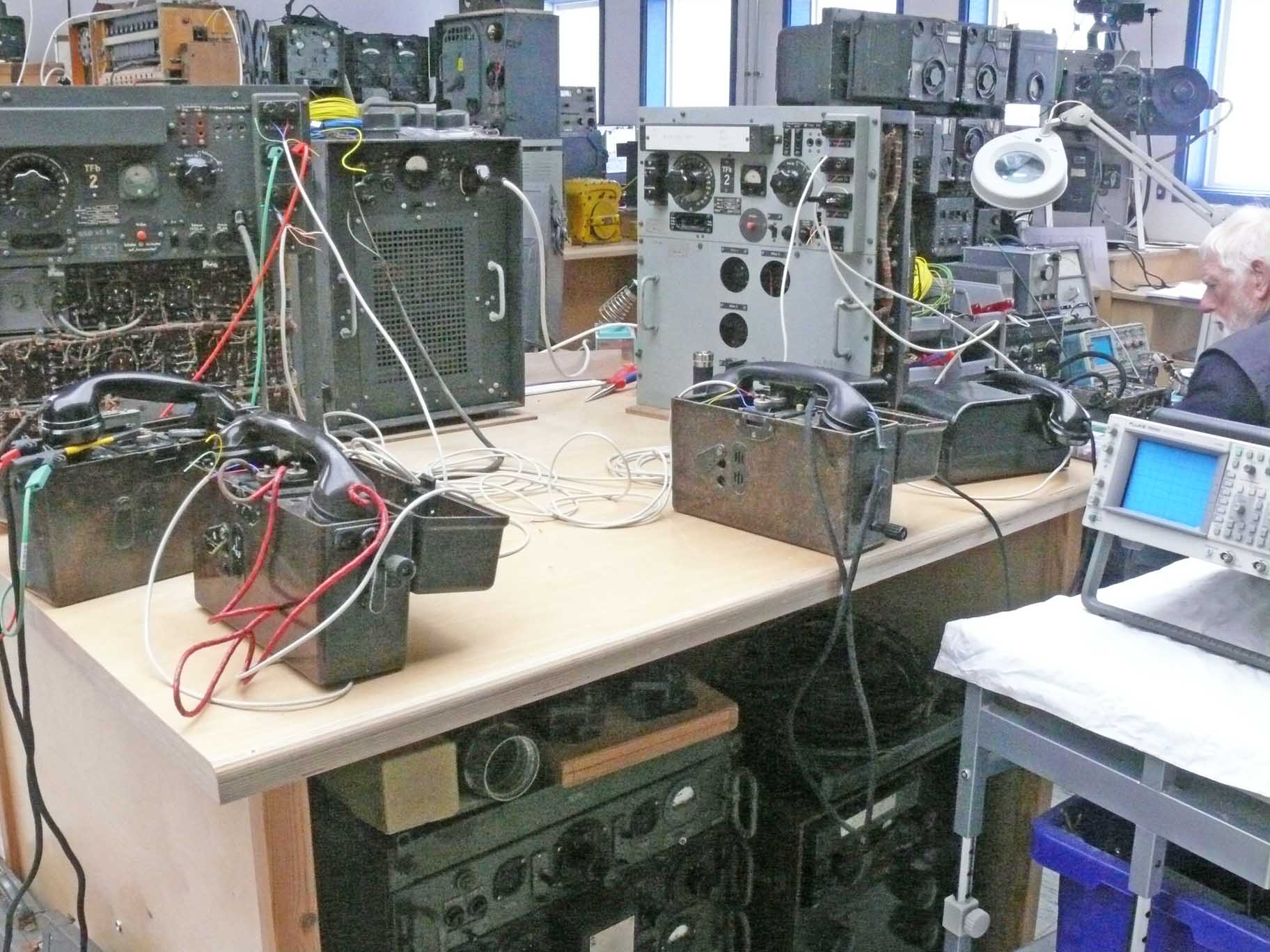
Once, it all started with the idea establishing a (field) telephone link system, as to bring visitors more in touch the way in the 1940s sites had been interconnected by telephone gear

Up on the left-hand side the telephone: 10 lines 'Klappenschrank' and also looking at the open rear side of one of our Tfb2s; which is being operated by means of 12 V dc
The latter has been mounted at a ball-bearing disk as to allow turning it a bit; by this means allowing visitors to get an impression of its construction inside.

The two brown field-telephones in front are interconnected by low-frequency means, like ordinary telephones (dc level)
The black one in front on the right is, in contrast, linked by carrier-telephony onto the telephone exchange by means of the 10 lines Feldklappenschrank; on the other end of our display the interconnection being maintained onto the next setup
The downside of such setup is that for a telephone experiment or conversation you always need someone at the other end of the line
Hampering, is the fact that when speaking the grip in the telephone has to activate the microphone (battery) current. It is astonishing to discover that most people do not understand how to operate it appropriately!
Often communicating this way ends up in a clumsy kind of experiment; whilst it is so simple pressing the telephone switch when talking.
It got the strong impressing that due to the curious circumstances most people aren't capable of speaking fluently more than a few words in the microphone.
What would be nice is next substituting a line- or cable simulating test box, between the two Tfb2 apparatus, as to simulate various line conditions.
But we do not possess such a device, and we have no idea where to obtain it!
To be continued in due course
By Arthur O. Bauer
![]()