
Mammut and Wassermann
Technology Survey
Prof. Hugh Griffith suggested we should call it
'Compulsive Hoarding'
In the foregoing webpage, and at the far end of this current webpage, I have explained that this does make sense.
Hoarding - was the Allied code-name for the Mammut installation; like was Chimney for the Wassermann system. We have to think of their typical antenna constructions, not about what was kept hidden within the bunkers below.
Photo 1 GAF Mammut*
(Courtesy Fritz Trenkle)
*The GAF operated four pylons, whereas the KM used three pylons, electrically there might have been not too much difference, because the adapted radar parts and techniques basically were of GEMA concept.
Let us start with the Mammut chapter first
A new survey on the Mammut radar system
In German language they would call this:
Eine Entdeckungsreise
Since recently, I encountered on various occasions the existence of the German naval (KM) Mammut radar system FuMO 51 - 52. Be it, due to excursions to V 143 bunkers or caused by the very nice and interesting French publication by Alain Chazette and his colleagues.
(Chazette)
Stations radar et radio-navigation
sur le Mur de l'Atlantique
Spécial Normandie d'Antifer à Granville
By Alain Chazette - Bernard Paich
and others
Published spring 2015
When you have an opportunity buy one!
ISBN 9 782915 767254
You can order it via their website directly
http://www.histoire-fortifications.com/index.asp
The previous webpage was recently initiated on 12 June 2012
Current status: 29 May 2022
Chapter 4 + 5a+5b + 6a+6b + 7-DvdB + 7-WaZ + 7-WaZ-2 + 7-WaZ-3 + 8 Dead zones + 8bc
+ 9 modified + 9a +9c + C + 9F + E
12 Crediting Colin Breach properly! (8-9'18)
13 New finding about the Kompensator-Stichleitung fitting (16-8'20)
On 10/10 2016 edited
(Rev)
On 20 November 2015, Henk Peek visited me in the museum and I did present my PowerPoint Mammut-Wassermann planned for the Open Museum Day (21 November); we discussed some details which forces me to revise- and add some consideration on the existing Wassermann webpage:
Revision
On 1st July I received two e-mails from my friend Phil Judkins containing the full version of:
Air Scientific Technical Translation
No. 1
on
Mammut F
Air Ministry A.D.I. (Science)
13/11/44
This latter office was headed by famous Dr. R.V. Jones
(I don't know whether he was then already a Professor)
Note at the front page

Reference 1 Quoting from the front page
(AIR 14 3614, NA KEW, courtesy Phil Judkins)
I have decided to add a special Chapter 4
Being engaged to the creation of chapter 4, I received, on 3rd July, some sensational photos from Mike Dean. Forcing me to revise quite some of my previous text; also owing to new reflections about thoroughness.
However, we got detailed photos which I have never encountered before; likely non of you either.
These photos had been taken shortly after the Germans surrendered and in the course of the British Operation 'Post Mortem' in Denmark in 1945.
I would like to stretch too, that those entering this particular webpage not for the first time, should have patience, and reading it all again first.
Please, start with this contribution from the very beginning again, because the now extended text and illustrations go often back to foregoing explanations.
This rather comprehensive, quite technical and unique, system explication, will hardly be found elsewhere on the world wide web.
Please sit down, be patient and take your valuable time. This chance you will never meet again!
Some of you could ask me, why not waiting until all is being processed?
My replay is - that most people browsing on the web are digesting big data on a very brief manner. Quick scanning through its content, and that's it; believing that they know it all now since!
This Survey is rather comprehensive, relying mainly upon sources, not accessible before. And, during the course of this Survey, new materials being brought in by equally minded friends. Therefore, its ultimate outcome is unpredictable.
You can follow my spontaneous emotions, and maybe also my errors; inevitably accompanying a survey. Some might get the impression that the sequence of details is not always logical; but, an explorer never knows what he is expecting the next day.
To me personally, reading and digesting the content of drawings and electrical schematics, and combining it instantly with all you have learned in the past, is an experience that hardly can be understood; when you haven't got the vibrating mood accompanying such a phenomenon.
Hence, there have to be, Deo volente, follow ups; so be it!
Before starting with this new webpage, I would like to stress the following concerns:
In this survey, like was done during the long lasting Nachtfee project, we have to building it up from all the bits and pieces where we have currently access to. This time, of course, doing it more or less virtually, as we do not possess the hardware, with some exceptions!
Doing it this way, might imply errors or incorrect estimations, but this is all in the game. I would say - inevitable by such an approach. On the other hand, it becomes an intriguing process, with potholes, of course.
Digesting Alain Chazette's wonderful book, I learned, that there existed a great difference between FuMO 51 and FuMO 52. The giant antenna system belonged to Mammut (FuMO 52). Its predecessor concerned a smaller system. Where the antenna and equipment is derived from a Seetakt system, though having a bigger antenna arrangement than the latter. During this survey we will learn, that the main differences between FuMO 51 and FuMO 52 was within the extended antenna design and changing to a lower frequency band, as was equally used for Freya systems.
After having read Alain Chazette's interesting book on radar on the Normandy coast (referred onto above), I contacted him and told him our concerns; that we would like to get permission for using some of the materials, particularly dedicated to Mammut and Wassermann technology. Merrily instantly he replied, and did send me a bunch of copies. Of course, asking me to acknowledge all appropriately. Though, he asked me also whether I can identify some pictures for him. Which was a pleasure doing it. It is, in fact, a knife cutting at both edges.
Chazette's interesting book is noticing details of say: FuMO 2 or FuMO 3 ... See-Riese ..., these particular kinds of details is not really my piece of cake. For me counts technology first. The outside appearance of a system might differ though, quite often, the technology inside is similar.
Starting this Survey
I was tantalized by the text integrated in the next photo

Photo 2 A N? display unit
(courtesy Alain Chazette, from his above mentioned fantastic book)
This sole photo might not be complete when it concerns a regular GEMA system.
Though, Alain Chazette provided another photo, which becomes the nucleus of our Survey.

Photo 3 Das Entfernungsübersichts (NB) Gerät
(courtesy Alain Chazette, from his above mentioned fantastic book)
This very informative picture might have been dropped due to lacking adequate contrast.
Let me first deal with what we can learn from it.
First: that it concerns a NB module, having a more or less equal designation which can be found within Freya and Seetakt systems.
Comparing these two photos with the following series, we will learn that this module is designed in many respect differently.
Since chapter 3 we know their CRT nomenclature.
Please bear in mind, the Kippspg-Erzeuger (Kippspannungserzeuger). To be translated in: deflection-voltage-generator. Kippspannung is mostly linked onto saw-tooth signals. Though, GEMA relied upon a different technique; they applied sine-waves. What they did, was using the particular part of the sine-wave where the up- or down wards going slope being considered sufficient linear. They did blank, however, the downwards going sine-wave slope. With this technology being dealt with further down on this webpage, we will learn, nevertheless, that the NVK NB apparatus used for deflection of the upper CRT indeed a saw-tooth signal.
Harry von Kroge pointed it is his nice book: Gema - Berlin, Geburtsttätte der deutschen aktiven Wasserschall- und Funkortungstechnik,
(5)
Quoting pp 71 - 72:
... Die Zeitlinie wurde horizontal mit einer Sinusspanning geschrieben. Die Auslenkung des zentrisch in Bildschirmmitte eingestellten Leuchtpunktes nach links und rechts erfolgte direkt mit der Tongenerator- Summerspannung (later known as Z-Gerät, AOB), die in einem Ablenkstrahlverstärker auf einen solchen Wert gebracht wurde, daß sie den Kathodenstrahl nach beiden seiten weit über den Rand des Bildschirmes auslenkte. Der auf dem Bildschirm sichtbare mittlere Teil der Schwingung um den Nulldurchgang war hinreichend gerade für eine lineare Teilung der Entfernungsskala. Mit einer speziellen Schaltung wurde erreicht, daß der Strahl nur im Vorlauf hell war; der Rücklauf war dunkelgesteuert. ...
However: Viewing the NB module of a Seetakt (Fu.M.G. 40 gB) apparatus (photo derived from this genuine manual) we encounter quite some differences.

Photo 4 Einsatz NB des Gerätes N
(Fu.M.G. (See takt)* 40G gB)
* This is no typos, but the actual text at the front-cover of this manual!
Viewing the NB module of a Seetakt apparatus
What both have in common - is that these carry the designation 'NB Gerät', further there is little similarity, but both carrying two CRT screens. However, this latter statement, we will notice in chapter 3, isn't correct. This emphasises what the module designation were about; it meant their purpose. The NB modules did have two CRT screens, of which the top one provided the overall measuring range (full range capture) and the lower one displays the accurate range reference marker. Normally, as we can see below, a NB module being just adjacent to the calibrated delay-line (Messkette) or within the N Gerät. But, we will also learn, that in some applications an NB like module being operated separately. This is being proved in chapter 3.
About 2011, I received an e-mail query, with attached two photos: asking us for what system this module might have been employed.

Photo 5 Another example of a NB display unit?
We will find out later, that this, most likely, should have to be called: P? Gerät!
(photo source, his first name was Colin ?)
(12)
On 8 September 2018 I received an e-mail on behalf of: Colin Breach, Rushmere, Lowestoft, Suffolk... He once did sent me photos connected to some queries. But I failed to recover his e-mail address but stored the attachment in a folder named only Collin; even spelling his name incoreectly. Later Phil Judkins pointed that this was in Britain an incoreect spelling of his first name.
He also pointed:
Good evening, have just been viewing your excellent detailed site about the Mammut radar system, and was surprised to see the pictures of the twin tube display unit, taken at the Norfolk and Suffolk Aviation Museum, Flixton, Suffolk, U.K.
Mentioned was the bright paintwork on this unit. I should explain that this display unit was found in a corner of the museum looking like scrap ready for the bin. After some work the unit was refurbished as sympathetically as possible too make ready for display, this is why it looks a bit too new. The range scales on the units I think I may have made up as the originals were missing, so marking are incorrect, probably..It is some time since I did the work.
I hope I have given him the necessary credit since today. The set indeed looks splendid, he pointed: too bright, but certainly nice it is.
In some respect this photo is too nice and clean; the paint is looking too 'bright' for a device of, say, 72 years old. But I guess, for some reason, that it might concern a range display once part of a Wassermann system. My first thought was Mammut, but later I discovered that this most likely isn't true! In what other long-range system it might have been once operated, stays open yet. I believe that Wassermann is most likely.
Please notice the mechanism on top of this photo, partly invisible; and compare it with the previous black and white photo derived from a Seetakt manual. It should be a magnifier lens, that, when pulled downwards, magnifies the displayed target traces on the two CRT screens. This provision equals the one shown on top of photo 4.
(E)
On 18/19/20 September 2015
Searching for new photo materials I came across Colin ?'s photos again and discovered that my previous reproduction was far too bright being put on the web. Consequently, additional information had been lost.
Below the first version, below it the new reproduction, which is answering many previous queries.

Photo 6a It is apparent that some information have vanished
(photo source, his first name was Colin ?)

Photo 6b Please compare this photo with the previous one
Viewing the 'P?' module from the right-hand side, which might have been once belonged to the P-Gerät which was part of the Wassermann radar system.
(photo source, his first name was Colin ?)
My guess - when looking carefully onto to both - the upper and lower CRT screens, where the range scales are well visible; albeit, that the actual range figures being blurred a bit. Though, what can be distinguished, is that the lower scale might carry two digit numbers whilst the upper range screen does carry three digit figures. Hence, the lower might cover up to 100 km and the upper CRT from 100 up to 200 km or even 300 km. This latter figure might well fit onto the range of Wassermann radar system - as well as it handles with a different scale division. Quite well understandable when dealing with far off target ranges.
Please notice, when looking carefully, that a very weak glimpse of range numbers scale just at the left-hand side of the upper CRT screen.
However
Interesting, the Germans quite often used plan- or flat- CRT screens, as to prevent reading-off errors (Paralax-Fehler). A comprehensive technique hardly found elsewhere, during these days.
The magnifier lens on top, is showing that it indeed concerns a (rectangular) lens.
When the lens-frame has been pulled down, it can be kept locked by means of the handle in front. In Gema systems generally, like for Freya and Seetakt, used two lenses.
However, we have to deal with curious differences between the displays shown at photos 2, 3 and 4. In contrast, the two photos 5 and 6 do have special provision at both sides of the CRTs. In the meantime, we have already discovered that we have to deal with a 'P?' display module, of which we possess no technical details, yet. It also is apparent, that all CRTs are having a 10 cm screen diameter.

Photo 7 AEG type HR2/100/1,5 A dual beam CRT, with special range scale provision
(This device is part of our collection)
(By the way, this CRT does no yet have a flat-CRT screen)
Though, Mammut and also Wassermann systems have to cope with ranges up to 300 km; in these cases they must have had an idea what target distance was to count with. This was my first thought, but I tend now to believe that only Wassermann was fit with such provision.
Later in the war, for instance in Radar News 19 (Funkmessnachrichten 19, issued 25 February 1945) they mentioned even for Freya the application of two CRTs where one is displaying the first half-, and the second CRT is showing the second half of the radar range.
This does make sense to me.
Considering photo 2 and 3
I would accept a
calibrated CRT screen, as is just visible at the upper CRT screen of photo 2.
Though, the lower
CRT screen does apparently lack a range scale. This might be in line with the
designation of: Beobachtungsrohr, call it observation scope. As we will notice
later, the GEMA range marker was a narrow pulse in the centre of the range
measuring screen.
(B)
Please notice:
Since 10 October 2016 we possess a working OB 110 projection provision!
I just learned, from the Seetakt manual (issued 1942), that this small marker was optically projected from behind at the CRT phosphorous-screen. I found, in the British Patent Office, already more than a decade ago the according German AEG patent DE 891577 application date: 2 November 1939.
This aspect just popped up in my mind!

Drawing 1 This revolutionary patent DE891577 CRT concept is, in my perception really clever
It allows light projection at the back-side surface of the phosphorous layer inside the cathode ray envelope. (3) constitutes a small slit. For it, the aqua-dag layer (6), normally running up to the CRT screen being left out partially. This means will be exploited in GEMA systems widely. All HRxx and HRPxx CRTs being manufactured this way. Most people don't have the slightest idea where this being meant for, and that it ever existed!
We later will learn how this practically worked out.
An additional 'reflection' on this technique:
Creating a comparable narrow sharp vertical line would apply for a quite high video bandwidth. Optically this is far more easy to accomplish! In my perception, electronically a technique in those days most difficult or even impossible. Additionally, the reference marker would drift (move) when the time-base centring being adjusted, making calibration hardly accurately possible.
Being this morning in the museum, I took the opportunity to take some photos of a HRP2/100/1,5A St
By the way: H = ? - R Röhre?; occasionally P = flat screen; 2 = two systems; 100 = 100 mm screen diameter; 1,5 A = ? - St might have stood for 'spezial Teilung'?

Photo 7a Viewing the AEG type HRP2/100/1,5 A St through the glass envelope towards the range scale. This scale might have been made before the phosphorous layer was deposited
(This device is part of our collection)
It is evident, that an optical slit projection can be accomplished from behind the phosphorous layer.

Drawing 7b Showing the main construction of the HRP2/100/1,5A and related CR tubes
The way these two systems being implemented is clearly visible; and are entirely equal. Providing even 8 deflection plates. The only matter both systems have in common is their filament (4 V)

Photo 7c This particular HRP2 ... CRT is being fit with a range scale running from 0 up to 200 km
(C)
On 13 September 2015
Frank Müller provided photos explaining how such projection system looks like
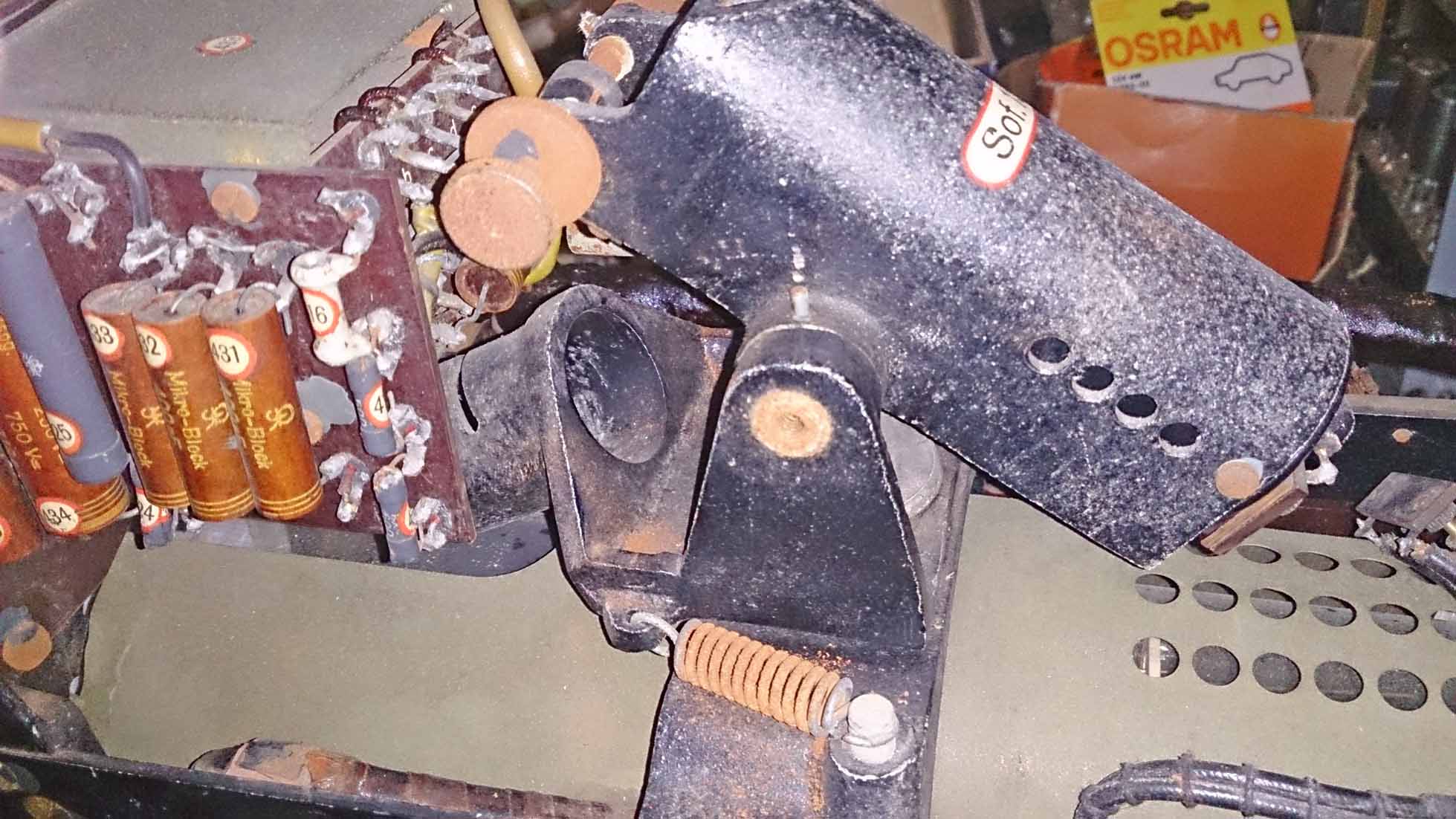
The long stretched housing marked Sof. 15 constitutes the light source. The black cylinder at about 30 degrees above the CRT is the optical projection system
(courtesy Frank Müller)
For more information details please In August/September 2016, via a contact of Phil Judkins, at a VMARS auction, we were finally able to obtain a complete OB 110 module fit with a complete projection system.

Since it is a popular device under demonstration
I really wonder, that the quite big lenses operate so sound
click at: OB-Gerät
and
second OB-110 Apparatus
Continuing with our Survey
Isn't it likely, that the two CRT screens at photo 5 and 6 did both carry once a range scale, like the above shown principle type? (Photo 7) On
When this is true, then it is not unlikely that the range was accordingly divided into two equal sections. What system did need two range divisions? My estimation, long range radars like (Mammut) and Wassermann. Freya or Seetakt, why should these?
Let us consider, until the contrary has been proved, that the upper range scale captured 0 - 150 km and the lower CRT was calibrated from 150 - 300 km.
However, some of you might say, I have read that the range of Mammut was 200 km!
What likely is being meant, is that the actual capture-range was 200 km (power - sensitivity limitations).
Like almost every GEMA related radar systems, it relied upon a PRF of 500 Hz (2 ms). Allowing a radar range of 600 / 2 = 300 km.
Likewise the small Würzburg, its PRF of 3750 Hz allowed a maximum cover range of 40 km, though they counted with 20 to 30 km regularly.
Let us continue with the two colour photos
Another finding from these two photos, is, that the lower series of potentiometer controls being linked to one another by means of (Bakelite like) gearing wheels. A system this way I never have encountered before. Sometimes potentiometer were linked by means of gears, but linking so many together?* On the other hand it might make sense, according the red-warning-sign at the gear-wheels, these potentiometers being connected onto high tensions. The CRT types used were HR(P)2/100/1,5A, it is thus likely that these operate with voltages of up to about 2 kV. Quite unpleasant touching!
* Like was done in Nachtfee, the purpose being, that when you deal with two beams at once, and in this case even with two CRTs, thus coping with four beams, that for convenience a single control is controlling brightness of all beams. Each HRx type CRT consisted of two fully independent CRT systems.
I would like to show you a schematic of the regular GEMA NB display unit

Drawing 2 Schaltung des Netzteil (of the NB module)
(Fu.M.G. (See takt) 40G (gB))
The aim of this technical drawing, is, to show you the rather complex arrangement of potentiometers involved in such a dual CRT display unit. Such as, shown on the photos 5 and 6.
What do you need more in a radar system?
A radar receiver

Photo 8 N Gerät
With attached range display
(derived from the Fu.M.G. (See takt) 40 G (gB) manual)
I estimate, that this display (OB Einsatz) shows the entire range captured, available at the video-output of the adjacent receiver module, on its right-hand side.
Please look closely at the CRT screen, you can vaguely see that this screen carries in front a range scale. Hence, the OB-Einsatz (module) did cover the full capture range of the system. There are quite many types HR2/100/1,5 (HRP 2/100/1,5 A) around ('P' stands for 'Plan' = flat) quite some carrying at their screen 'range markers' between 0 and 150 km. It is therefore quite clear that they necessitated a fine-range screen for precision measurement too; like the one designated 'NB Gerät'.
However, working on range measurements, I discovered that on photo 8 we see only a single CRT display (OB). For which I already estimated that it concerns full range coverage.
But, we have dealt with two NB Einsätze (modules) having two CRT screens. Nx is always part of the main frame unit N.
Searching in the Seetakt manual, I came across another unit (frame) N fit not, as is shown in photo 8, though being equipped with two CRTs.

Photo 8a Inneres des Gerätes N
Viewing what is inside the N Gerät
(derived from the Fu.M.G. (See takt) 40 G (gB) manual)
Here the receiver being designated with NE and the NB module being more or less similar to the previously shown examples
Please notice also the quite many gear-wheels linking potentiometers together.
Below is shown how the Freya receiver actually looks like, in their outside appearance there is not too much difference between Seetakt and Freya modules.

Photo 9
The Freya receiver module, which we kindly have on a long-term loan, from Jan Wolthuis
Jan Wolthuis died sadly on 3rd October 2015. His wife most
kindly donated this nice receiver module to us! A donation we do appreciate very
much!
It constitutes a real great contribution
to our collection.
We also need a:
Transmitter

Photo 10 The Freya transmitter unit (Gerät T), was such a system employed in conjunction to the Mammut system?
(source TME 11-219)
We know now it was, because of the drawing of the bunker layout discussed below in drawing 2. It potentially could be converted into a rather powerful system. Like was done for application in the Jagdschloss system. The major difference being, however, the Jagdschloss transmitter was equipped with a provision for quick frequency change (Wismar). Later I will express below my doubts whether high power transmitter were used; at least unlikely in conjunction to Mammut.
The Freya system relied upon grid keying of a pair of TS 41 valves (or TS 4 for lower power application). Though, like was done for Jagdschloss, where they changed over from grid-keying onto anode-keying. In the case of Jagdschloss, a special, separate modulator provided up to 30 kV anode pulses.
Please notice what was stated in the Jagdschloss trainings manual:

Reference 2 Der Breitbandempfänger soll an Stelle des NE-Gerätes in den Jagdschloss, Wassermann und Freya-Anlagen verwendet werden. Er gestattet die verstärkung von Impulsen über einen grossen Frequenzbereich.
(Jagdschloss instruction manual)
What we learn is that Jagdschloss, Wasserman and Freya systems had some similarities; we have seen already that Freya and Seetakt systems do have also much in common. It is therefore allowed to designate all systems being derived from a single system family. Seetakt existed just before Freya, I therefore opt that Seetakt may be regarded for being the nucleus of the GEMA concept.
With some hesitation
Let us return, after this brief interlude, to the queries around the Mammut and/or Wassermann transmitters.
Fritz Trenkle, to whom we all owe quite much, sometimes exaggerate figures, as, for instance, a transmitting power was discussed or planned for a certain value, he often quotes then that the power was up to ... .
We dealt before with enhancing the transmission power of the regular Freya system.
It was already noticed, that Siemens enhanced the transmitting power by changing the keying-method of Freya like transmitter. Changing over from grid-keying at + 8 kV anode voltage, to anode-keying at 30 kV.
Strange?
No!
The so-called R Gerät (shown at photo 12) constituting the power supply of the transmitter system, provided maximally, say, 8 kV +. How could they then get 30 kV? Please consider for details the Jagdschloss manual and what is accessible on our website.
Let us consider a pulse-amplifier, where the output transformer is of special design and being loaded by the anodes of the two transmitter valves TS 41. Thus, the transformer secondary output is directly providing the anode voltage fed onto the push-pull transmitter.
In this case the transmitter is capable of generating far more energy than with the regular grid-keying mode (where the anode is getting continuously + 8 kV, and the transmitter being triggered by de-blocking the negative grid bias).
We have then to
count with up to 100 kW. Please bear in mind, that 100 kW is being delivered for say
1 to 1.5 µs; repeating 500 times per second. Hence, the system theoretically
consumes: 1.5 10-6 x 500 x 100 = 0.075 kW (75 watt per second
J/s*).
Seemingly not quite much. The main burden have to carry the
blocking capacitors in the power supply,
the TS 41 filaments, and the modulator
transformer, because these have to deliver within short-burst-durations quite
high currents for 1.5 µs, this 500 times per second.
* Recently Dick van den Berg pointed correctly, that the physical notation should be Joule per second
Let us estimate
that the design of the transmitter was sound and an efficiency was reached of,
say, 60%. The loss being 40 % of 100 kW = 40 kW. The anode modulator had
therefore to deliver 100 kW + 40 kW = 140 kW. This will causing a power
consumption of 105 W per second
On 27 June I received an e-mail from Frank Doerenberg with
a valid complain, that the power which should be additionally supplied should be
100 : 6 = 167 kW. The equation becomes now 125 W (using the previous equation).
(D)
On 31 October, at the annual Hell meeting held this time in Eindhoven, Rommert Zonneveld did bring my attention onto the fact that my previous correction initiated by Frank Doerenberg does still contain a fault. (just a few lines ago dealt with)
He correctly lays his finger on a mistake I have made
I wasn't grasping the full consequence, and have had to re-read first (the next day) my previous way of thinking.
Let us please reconstruct what it all is about.
The fact: that, although, the Mammut power might once have been estimated for 100 kW (hypothetical), that the energy consumption is only 0.075 kJ/s (kW). When we estimate that the efficiency of the output stage is 60 % the calculation should become:
100 : 60 = 1.66
We have thus to multiply our foregoing 0.075 kW by the loss factor 1.66, resulting in an energy consumption of: 0.125 kJ/s (125 W)
When we use the figures provided in the Jagdschloss manual, the anode pulses reached 30 kV. For simplicity, we estimate that energy does not suffer from slope-response and other losses; Hence, the full energy has to be provided during 1.5 µs. (in practice this wasn't the case)
P = I ● U → I = P : U → 100,000 : 30,000 = 3.3 A. The modulator transformer should provide 3.3 A for a duration of 1.5 µs; though, 500 times per second.
In some source is quoted 200 kW output to the Mammut transmitter. I have no idea how such a transmitter should have looked alike. It might have been even of special NVK design. Noticing the statement in reference 1, we might consider that in some way or another, some techniques used in the Jagdschloss system was also adopted within the Wassermann system. Siemens was also involved in the design of the Wassermann (a contractor). I don't know when Siemens became engaged.
We later will see (photo 15), just at the edge of a photo, taken during Operation 'Post Mortem' June early July 1945, that a regular T Gerät was present at the Blavadshuk 'Mammut' site in Denmark.
When you would ask me, whether I believe that high power radar systems were standard German practice? I have honestly to reply: I don't think so.
We therefore must count with realistic transmitting power, and most Freya - Seetakt and even Mammut relied upon a power of 8 to maximally 12 kW (with some particular exceptions). The Germans relied on big antennae and moderate transmitting power. That is the reason why they did built such gigantic systems, like Mammut and Wassermann. Even the Giant Würzburg (Riese FuMG 65) may be add onto this group. We neglect, by the way, that they regularly operated at relatively low frequency spectra, and therefore were obliged to opt for big antenna systems; as to keeping up with good system results.
(A)
Also essential is knowing about the target distance:
Range measurement

Photo 11 O Gerät
(derived from the Fu.M.G. (See takt) 40 G (gB) manual)
Please notice also our Exhibits-details 17 webpage, where you can see in great details our recently obtained OB-Gerät (plug-in module)
On the right-hand side the OK Einsatz (Messkette) and on the left-hand side the OB Einsatz (always having a single CRT without range markers), though being equipped with a projected light-marker-line from behind (Lichtzeiger).
When you look closely, you can see that the CRT is not been fit with a range scale.
It is therefore quite clear, that the purpose of this CRT display was directly linked onto its purpose; measuring range.
Please, consider also the range scales of the OK Einsatz (plug-in) and the mechanical digital read-out.
You might have noticed - that I have decided to jump with you into a quite deep pond.
To day, I had to copy some schematics from the Fu.M.G. (See takt) 40G (gB) manual, and concluded that among other schematics, it would make sense to copy the Messkette (OK Gerät) schematic as well. Even when you cannot understand it, it might give you an impression of its very complexity. Most of the components were of rather high quality; we have to think of 0.1 to 0.5 % tolerances. Most capacitors were of the mica-silver types and kept hermetically sealed-off from environment within solid ceramic housings.

Drawing 2a Schaltbild vom Einsatz OK
(derived from the Fu.M.G. (See takt) 40 G (gB) manual)
To open it in PDF, please click at the above drawing
The schematic of the rather complex delay-line used for accurate range measurements.
Overlooking now all the foregoing considerations, in respect to the NB modules. Is it valid to consider that the module shown on photo 5 and 6 belonged to the function of a NB Einsatz? No! New docs provided kindly by Alain Chazette, shows that at least Mammut operated a NVK designed NB display (photos 2 and 3). We just have found, but not yet put on the web, that the Wassermann system did have an additional 'P Gerät', which, I suppose, may be linked onto the display unit shown on the photos 5 and 6.
Do we have to wonder? Not particularly, because our references are based upon Seetakt and Freya related modules. Freya possessed an average range of, say, 100 km. Whilst Mammut and Wassermann have provided ranges of >> 200 km.
Another consideration:
We possess the genuine manual to Fu.M.G. (See takt) 40 gB) and therefore can rely upon this valuable source of information.
The early Mammut system carried the KM designation FuMO 51. It used mainly Seetakt technology, including its operational spectrum of ≈ 375 MHz (λ = 80 cm). The, what we call, Mammut (FuMO 52) relied on similar technologies, but actually operated within the Freya frequency spectrum (≈ 125 MHz, λ = 2.4 m). My estimation: - because in this spectrum valves could provide higher energies. And, transmission energy was what counted most; also, the higher the frequency the lower the receiver sensibility is. This is a fundamental rule. Hence, operating a lower frequency spectrum, had a double advantage, more receiver sensitivity - as well as more transmission power. But, one fundamental matter is countering the longer-waves advantages. That is: antenna gain. An antenna can then be made smaller, or with the same dimension, creating a higher 'bundled' radiation pattern as well as power (smaller aperture provides then, more energy per square unit). Fundamentally, when an amount of energy being concentrated at a smaller dimension, the energy per square unit is increasing*. Giving you a brief, but rather, crude example. Everybody might have once seen gramophone pickups fit with sapphire needles. Do you realise, that the tip of a sapphire is pressing with about 1 ton (per sq unit) at the gramophone disk micro-grove surface? All the pressure being concentrated upon a very small spot.
* It actually is the relation between the concerned wavelength versus dimensions of the bundling device; be it an antenna- or an optical arrangement.
Going for the application within the apparatus bunker
Let us now consider information we got from Alain Chazette from his above mentioned fantastic book on German electronic systems engaged on the Normandy coast; referred onto above (and much more!).

Drawing 3 Viewing a genuine German wartime drawing, shown is briefly the arrangement of the various modules engaged
(NARA, with courtesy of Alain Chazette, from his above mentioned fantastic book)
We will further down see, that in practice some did look a tiny bit different
(2a)
What we, nevertheless, should consider, is that we have now information on the special designed NVK NB display unit. We can also learn from drawing 13, that the schematic was dealt with in February 1943 and thereafter; it is therefore not unlikely, that considering military practice, it should have become available not before the second have of 1943. This drawing 3, might therefore reflect what became the general outfit of Mammut stations.
Further down we are able, thanks to Mike Dean, to see a real station picture taken shortly after the Germans did surrender in Denmark (1945); and this is, with a very tiny exception, in accordance to the above shown drawing 3.
Let us concentrate our attention first at the cross section of the bunker (upper room)
We neglect on the most left-hand compensator and consider only the right-hand unit. Because its existence is for our system understanding not essential. An example of 'T' is shown on photo 10.
Please see later 'Eureka'.
On the other side of that boarding wall, we see the column fit with a wheel for steering the compensator - thus the direction of the actual antenna beam; having on top of it Gerät N; from this just mentioned new picture, we know now that it actually was standing at a table behind the steering column.
About the middle of the table we see module Z. This is the general time-base, providing accurately 500 Hz timing signals. (To be dealt with some photos below)
Next we see the O Gerät of photo 11
This is constituting the range-finder delay-line (Messkette OK) combined with the CRT display Gerät OB. My first thought was that the Messkette should have been adapted for the double range of Mammut. But this wasn't the case; the Z Gerät (time-base) was connected onto a switch, which allowed, at will, to switch over to the +150 mode. This mode rotated the signal phase fed onto the O-Gerät for 180°; the range read-off was to add an additional + 150 km. Extending the range up to 300 km. (Dealt with later)
On the far right-hand side we encounter Gerät R, constituting the medium and high voltage power supply.

Photo 12 The R Gerät, the main power supply of most GEMA related radar systems
(Part of our collection)
The text onto both circular controls being Dutch language, because once this unit was in post war days operated in a Lab of a Dutch Technical High School, now a Technical University.
We continue with the Mammut antenna

Drawing 4 Mammut F, a GAF adaptation of the regular Mammut, though being fit with back-to-back antenna arrays. We neglect the backside of one of the antennae, as this is not essential for our understanding
(with courtesy of Alain Chazette, from his above mentioned fantastic book)
We notice a bunch of coaxial antenna cables fed from both sides of this huge antenna array.
By means of virtually changing the phase-ratio of the left-hand versus the right-hand cables vice versa, it becomes possible to steer the antenna radiation pattern. This was accomplished by a so-called compensator. The word compensator implies compensation. When one side got, virtually, a shorter cable length of say the value '-Υ' this value was virtually substituted onto the opposite side with the value '+Υ'.
This implied for the many antenna cables involved a rather complex, and accurate, mechanical device.

Photo 13 Der FK2 Kompensator
(with courtesy of Alain Chazette, from his above mentioned fantastic book)
From this genuine document we know that its designation is FK2. However, the index 2 might also indicate that there might have been involved a type FK1 as well.
Please notice, we have received new pictures from Mike Dean, these might not give the full shape of the compensator device, but are showing us how it in practice was be interconnected. What I designated being moving arm stops, were actually coaxial connectors, meant for coaxial-line-matching! And, there where rather many of these in use! (dealt with chapter 4)
All the coaxial antenna cables involved being connected onto both coaxial-tube ends left and right. The arm in the centre is virtually steering the antenna beam radiation-pattern. Being controlled by a special steering column.
Please look closely at the arm and the coaxial tubes!
For myself for the first time, I become aware how this arm actually interacts.
Phil Judkins recently provided A.D.I. (Science) No 1 report of 13/1/1944
In it is dealt with contradiction figures, of which I cannot judge its correctness. We therefore, have to consider my estimation below; as reflecting only a situation not being the accurate matter of facts
The signal pick up from each coaxial line is equally accomplished as is done by means of slotted lines, though now, most likely, touching the core of the coaxial system. In my perception, the slots being quite broad, but might have been necessary because of the quite high voltages involved*. Slotted line probes just don't touch the coaxial core, but in this case this would provide a capacitive (division) loss. Which includes a reception loss as well. Thus, should have been prevented for.
* When we consider that: P = U ● I → I = U : R the equation can also be written: P = U2 : R → P ● R = U2 → 100,000 ● 70 = U2 → U = 2645 V ac. 2.5 kV HF voltage cannot be neglected in a quite open, often rather humid, environment! (R is constituting the impedance of, say, Z = 70 Ω). When the impedance would be counted for 70 : 2 = 35 Ω we get: 1870 V ac; considering that at the compensator-governor we have to notice that two coaxial systems of, say, 70 Ω being operated parallel. The impedances, when matched soundly, these behave like two parallel resistors, in this case two equal resistors (70 : 2 = 35).
The A.D.I report No. 1 (dealt with in chapter 4) on Mammut F provides the information (page 5) that the coaxial cable type was VACHA 726 having an impedance of 60 Ω. Not unlikely, because the coaxial cable, to what I have seen in the V 143 bunker at Wijk aan Zee, were quite heavy and did have solid dielectrics. However, our calculation will not change much of the values calculated previously. Not dealt with in the A.D.I. No 1 report is the fact that at the pick up point of the compensator slider we have to count with an cable impedance of 60 : 2 = 30 Ω .
The upper coaxial tube pointing right-wards might have been the combined (single) coaxial interconnecting cable linking it onto the radar system. However, we will learn later, that combining the various cables was a bit more demanding then simply combing them.

Photo 14 Die Steuersäule (designed by NVK)
(with courtesy of Alain Chazette, from his above mentioned fantastic book)
The steering wheel did control the motor driven compensator. But wherefore these two foot-pedals?
When we look closely at this compensator (photos 13, 14 and drawing 2), we can see that an exact system operated in parallel. Was this particularly meant for application within a GAF Mammut F? Is the dual function reflected in the nomenclature FK2, I don't yet know. Or, was this owing to the special design of the Mammut antenna?
We don't know yet.

Drawing 5 Schaltbild Kompensatoren-Doppelsteuersäule (design NVK)
The electrical schematic to the NVK Steuersäule
(with courtesy of Alain Chazette, from his above mentioned fantastic book)
Very intriguing, Sperrtopf being translated into English: Cable zeal. It becomes quite apparent, the this English speaking person did not understand the implication of German technical expressions. Sperrtopf, which means: blocking off pot, likely consisting of a kind of 'wave-length' matching provision. Will be dealt with later, as we found also a document on this aspect.
Very recently we got - most kindly - a selection of utmost informative photos from Mike Dean.
It is most apparent, that the English speaking person writing on this subject, does not possess too much experience with coaxial antenna techniques!

Photo 15 Viewing on the left-hand side the coaxial antenna cables, the right-hand group for the receiver and the left-hand group for transmission (connected on the left with the compensator). Please look at the right-hand side provision, constituting a coaxial balance-to-unbalance facility, also known as balun! Balance output onto a un-balanced coax line. This is what the Germans designated Sperrtopf - a provision to block for symmetry-asymmetry vv. However, owing to its construction, being valid for a particular frequency (band) only!
(111 SC 269018 - "US National Archives" courtesy Mike Dean)
The left-hand flexible tube provides regular air-cooling.
Please notice the coaxial cable (type Vacha 726) mounted just underneath the bunker sealing. It might have been of an equal type as is to be dealt with further down.
Nevertheless:
Please, bear always in mind, that drawing 5 is valid for the GAF Mammut type F. The second compensator being skipped in normal Mammut systems.
What is better than having genuine schematics at hand?
What can we learn from it?
Very important, is, that the pedals allow at will to select which antenna side is to be operated (front or back). Of course, only valid for the GAF Mammut F version.
The electrical changing-over selector is providing which side is to be operated.
When you look carefully, you can read Kompensator für vorwärtigen Spiegel linked onto the right-hand side scale; the left-hand meter scale was meant for Kompensator für rückwärtigen Spiegel (backwards viewing system)
Heureka!
This drawing gives the clue why the compensator is being designed in a dual way (though, within the same compensator mounting frame). One being meant for the receiver and the other one being operated for the transmitter. Please look, for better understanding, at photo 13 showing compensator type FK2. Separate transmission and receiving was similarly accomplished for regular Freya as well as Seetakt systems. These systems lacking a compensator as well as a T/R switching; in German language 'Simultan Gerät'!
Consequently, the complexity of the Mammut antenna array decreases quite much!

Drawing 4a Please look closely at this modified drawing again. You can see, that the antenna-array is consisting of two equal systems stack together. One above and the other one below the dotted red line. According the Fu.M.G. (See takt) 40 G (gB) manual, is the section designated here 'I' used for the receiver- and section II is operating in conjunction to the transmitter TU unit (T Gerät). It is therefore not unlikely, that the same practical solution was adopted here too.
(with courtesy of Alain Chazette, from his above mentioned fantastic book, and my additional brief modifications AOB)
Thanks to Alain Chazette we can provide the principle upon the directional property of Mammut

Drawing 6 Zur Richtwirkung einer Dipolgruppe (date 12 January1943)
(with courtesy of Alain Chazette, from his above mentioned fantastic book)
Nachrichtenmitterversuchskommando Pelzerhaken
This NVK drawing, showing the principle of directional antennae steering
In this case they refer onto a Freya antenna array.
In this drawing the motion (deviation) of g/2 is constituting a certain deviation out off the centre position of the antenna-compensator; causing a virtual swing of the antenna-array radiation pattern.
But, we have discovered, that, principally, the Mammut antenna array was actually a bigger version of a Freya and Seetakt antenna array. Of course, neglecting the implementation of a (directive) compensator.

Drawing 7 An example how such kind of antenna systems being interconnected and being mounted at the metal mirror (reflector) frame
(with courtesy of Alain Chazette, from his above mentioned fantastic book, modified AOB)
The mounting rods ending at square-plates - red-encircled - are directly mounted (standing) at the earth plane of the antenna mirror; in A.D.I. No 1 report being quoted - that the standoffs were insulators, but from other sources I know that they used metal mountings. The towards us going U-shape loops constitute ¼ λ (quarter-wave) stubs (actually the U-shape causes 2 x ¼ λ = ½ λ rotation)*. The, blue encircled, two wires going through a single hole constitute the (symmetric) antenna-feeders; feeding onto (from) a balun like provision (Sperrtopf) (Deo volente, being dealt with in future chapter 5).
This kind of antenna array nearly always stood (were mounted) at the metal mirror frame. Hence, all antenna elements were connected in a galvanic manner onto ground; becoming insulated from ground virtually due to the ¼ λ stubs acting only at about the operational radar wave-length. Thus only becoming active when being operated (activated) at an appropriate frequency. This fact called for a different design when broad-band operation became necessary.
* Not always mentioned, but like wire antennas, our Mammut antenna dipoles (half wave), do have an actual antenna size (length) multiplied by a factor of 0.48. In case of our Mammut (½ λ) antenna dipoles: (2.4 / 2) x 0.48 = 0,576 m = 57.6 cm in stead of 60 cm. (V/c = 96 % - thus giving a 4 % length reduction). The technical and theoretical reason for it being omitted in this context. These figures being provided in a wartime ZWB- Berichte report: Grundlagen der Breitbandantennenanlagen by O. Zinke
We will learn later, that Mammut might have been operating at different frequencies, but the systems hardly were tuneable, owing to the unimaginable complicated matching provisions.
Another, not yet dealt with aspect is the fact of enhancing the double range displays.

Drawing 8 Anschluss des Messzusatzes "+150" im Gerät Z 100
Funkversuchsstelle Pelzerhaken
(with courtesy of Alain Chazette, from his above mentioned fantastic book)
What is unknown to me, what is being meant with: zum Steuergerät; what particular unit is meant here? What means: zu Kl. 9 (OK-Gehäuse) (für NB Gerät)? Kl. should have stood for: Klemme oder Klemmleiste 9.
Anschluss des Messzusatzes "+ 150" puzzles me also. Would this imply, that a kind of dual range display was dealt with like the one in the photos 5 and 6? We don't know.
We will further down learn, for what purpose this modification was being meant for.
Please notice that the schematic was approved on 15.3.1943! It therefore might not have been implemented in all Mammut systems.
Very interesting detail!
Here we notice that a special CRT deflection adaption was commenced, called: + 150
Z 100 was the time-base generator, which will be dealt with as well.
For us also significant is the information at the lower schematic, which points onto the NVK NB display apparatus; dealt with in the photos 2 and 3. Is to be dealt with in details, in due course.

Photo 16 Einsatz des Gerätes Z
The Z Gerät module (Z 100)
The time-base reference of almost every GEMA related system
(Fu.M.G. (See takt) 40 G (gB) manual)
This basic unit can be find in all Freya - Seetakt - Mammut - Wassermann - Jagdschloss and related systems. Albeit, that each system necessitated some minor adaptations.
The next schematic is showing you the essential electronics of a Z 100 Gerät

Drawing 9 Schaltung vom Frequenzgenerator (Summer)
(derived from Fu.M.G. (See takt) 40G (gB))
Before you all get lost in the many sub units creating all together a GEMA system , we should digest its basic principles first.
J816 ↓↓↓↓↓ J816return P826 ↓↓↓↓↓ P826return

Drawing 10 Darstellung des direkten und des Reflexionsimpulses auf dem Braunschen Rohr
The very brief explanation of the Seetakt and Freya related systems
(Fu.M.G. (See takt) 40 G (gB) manual)
This principle schematic is self explaining.

Drawing 11 Frequenzverlauf im Dete-Gerät
The principle drawing of the Seetakt system
(Fu.M.G. (See takt) 40 G (gB) manual)
Chose yourself what drawing fits best to you.
'Summer' means: 'tone frequency generator' (in our case 500 Hz)
Please notice the vertical red line, which constitutes the reference light-line, optically projected from behind (rear) at the phosphorous screen layer (Lichtzeiger).
Please notice the green sine-wave signals which constitute the deflection signal, or as is designated in photo 3 'Kippspannung' means not a saw-tooth, but a sine-wave signal being operated. Though, we later will learn that the NVK NB Gerät used for the full range screen capture display indeed a saw-tooth deflection instead.
On 29 June 2015
Chapter 3
We continue our Survey
One of the striking techniques mentioned within this survey, is the matter of projecting an optical reference line from behind towards the phosphorous CRT screen layer; like is shown in the next drawing 10.

Drawing 12 Schematische Darstellung der Eichung und Messung (für 500 Hz)
(Fu.M.G. (See takt) 40 G (gB) manual)
The system diagram concerning range calibration and measurement
Please notice the optical reference line 'Lichtmarke'.
This block diagram shows, for drawing simplicity, two CRTs; although, it concerns a single one, operating for two options: for setting the so-called zero-setting (Nullstellung)(upper drawing) and in the second situation for real range measurements (Meßstellung) (lower drawing).
Down we can read the Fu. M.G. (See takt) 40 G (gB) genuine text:

Reference 2 ..... Um bei Betrachtung des Schirmbildes Paralaxfehler auszuschließen, wird die Nullmarke von hinten auf den Leuchtschirm des Braunschen Rohres projiziert, in dem ein enger Spalt von einer Soffittenlampe* beleuchtet wird. Das durchtretende Licht erzeugt mit Hilfe einer Optik auf dem Leuchtschirm (phosphorous layer, AOB) ein Bild, das durch Schwenken des Spaltes und durch verschieben der Optik scharf eingestellt werden kann. .....
(Fu.M.G. (See takt) 40 G (gB) manual)
* Soffittenlampe

Photo copied from: http://www.ersatzteilbox.com/product_info.php/info/p67429_Soffittenlampe-C5W-12V-5W.html These lamp types being still available and were (are?) widely used in cars for all kind of purposes. Its advantage, is, that the filament shining being stretched and therefore is illuminating in a broader way.

Drawing 13 Schaltung für Entfernungs-Übersichtsichtsgerät (NB-Gerät)
(with courtesy of Alain Chazette, from his above mentioned fantastic book)
A most rare technical document, considering the electrical schematic of the special NVK NB display unit shown in the photos 2 and 3
My first attention is upon the two CRT deflection systems. Seemingly, these were single systems, in contrast to the regular HRx2xxx types. Viewing better the details of this drawing, we know since that the AEG CRT type was: HR1/100/1,5 being operated. Following the nomenclature, it concerns a single beam - fit with a 100 mm screen diameter.
This finding changes our knowledge quite much:

Photo 17 HR1/100/1,5
Photo copied from: http://www.radiomuseum.org/tubes/tube_hr110015.html
It becomes evident, that this CRT type possesses equal facilities as to project a light-slit (line) from behind at the rear side of the phosphorous screen layer; as does have the regular HR 2xxx series.
Let us explain briefly the schematic
Down on the far left-hand side we see the connection point 'b8'. This signal, likely originating from the Z 100 unit, is being fed onto a circuit known as an all-pass network. Its only purpose is shifting controllable the signal phase over 90 degrees, theoretically valid for over a wider bandwidth*. Signal being amplified and then fed onto a Valvo (Philips) type '4690' thyratron** Its signal reaches connection point 'B', this signal also being inverted by valve '96' and therefore being phase-shifted for 180 degrees, being provided at point 'A'. These two signals 'A' and 'B' being fed onto the horizontal deflection plates of the upper CRT on the most left-hand side (Oberes Rohr).
* Please consider the potentiometer '105' in the above schematic, this is most likely the control designated 'Phase', in photo 2.
(6)
** By the way, thyratron - this is a device well suited for generating saw-tooth signals. This might imply, in contrast to other CRT displays operating in conjunction to regular GEMA systems, that the upper CRT in the photos 2 and 3 did rely upon a saw-tooth deflection signal. Its actual signal 'phase' presented at the CRT screen could be varied. The hole allowing 'Phase adjustment' was likely meant for presetting; otherwise it would have been fit with a regular control-knob. However, we may estimate, that the lower CRT (unteres Rohr) is getting a sine-wave fed onto the CRT deflection plates (originating from the Messkette). Where the downwards going slope being blanked. The upper CRT (oberes Rohr) is lacking a blanking provision. Notice Harry von Kroge's explanation 5 Digesting all this, it is, in my perception, not unlikely, that the lower CRT could have been fit with an optical 'Lichtmarke' or reference line. We may estimate, that calibration was accomplished like is shown in drawing 10.
My guess, the horizontal signal necessary for the lower CRT, like is done within regular NB module, this time-base-signal being provided by means of the variable delay line, which is calibrated in range steps (Messkette) (please, notice also drawing 10, where its brief principle being dealt with). This delayed signal being fed on the upper far right-hand side, onto the connections b1 and b2; being amplified and fed onto the secondary push-pull 'bobbin' of the (output) transformer. This is providing two 180 degrees shifted sinusoidal signals against ground. These signals 'C' and 'D' constituting the horizontal time-base to the lower CRT on the most right-hand side (Unteres Rohr). We do not wonder much that both top vertical deflection plates being wired parallel and getting, most likely, their signals from the common 'video output' of the receiver module NE.
The components: C 52 - 53 - and 54 together with R 55 - 56 - 57 constitute a phase shifting network. To my understanding, after amplification in valve 59, and therefore rotating it 180 degrees, this signal being fed onto the Wehnelt-cylinder of the lower CRT. This signal should blank (suppress) (Rücklaufsperre - dunkelsteuerung) the unwanted part of the sinusoidal time-base-signal.
It just popped up in my mind again:
Photo 2 Please take a close look at the lower CRT and view carefully the lower centre of the white phosphorous layer. We might see some (darker) trace of a vertical line
(with courtesy of Alain Chazette, from his above mentioned fantastic book)
'Null Korrektur' is adjusting the horizontal position (lower screen) of the reference pulse versus the optically projected vertical light-line from behind the CRT screen (consider for better understanding drawing 10 again)
Amplitude, might have concerned potentiometer 86, which is controlling valve 83, the latter constituting a 'current-source'. The combination of a current-source and a thyratron is best fitting for generating a sound saw-tooth signal.
Let us now taking a closer look at:
Photo 7c Don't we recognise a black trace under the 100 km marker either?
(our own collection)
It might be imagination, but in both cases there are brief signs of a darker straight line.
One fact is countering this, because this latter CRT type should not have been operated for full range coverage.
However, looking closely at the NVK NB photo again, there doubtless is a darker straight line; running from below upwards.
Nevertheless, curious it still is.
Let us continue with the schematic drawing 11
The lower CRT (Unteres Rohr) is being blanked, though, the upper CRT (Oberes Rohr) apparently not.
Another interesting fact is the connector designated 'Abb. 13'.
This connector equals the connector types used by Telefunken in their Köln E 52 xx and Ulm E 53. Though, as we have recently learned from our Stuttgart Fu G 03 module, this set employed these too. I believed that these smart universal and modular connector type was a Telefunken product, which might, after all, not have been the case. As it apparently was being used for quite many applications - by different institutions. However, smart these were; in post war days adopted widely by the Russians either. One additional query concerns 'A' and 'B' at connector points 1 and 2. Does this imply, and why not, linking the current status of saw-tooth provided at deflection plates of the left-hand CRT, had been necessary for an additional display?
May be.
About some test gear
Quite important was to check what the current radar frequency is; some source quote within 100 kHz (0.1 Mc/s):
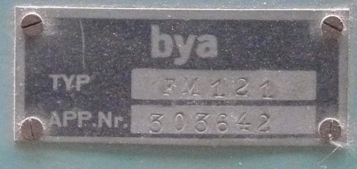
Photo 18 Typ FM 121 (Frequenzmesser)
App. Nr. 303642 (coded serial number)
bya manufacture code for GEMA
(our own collection)
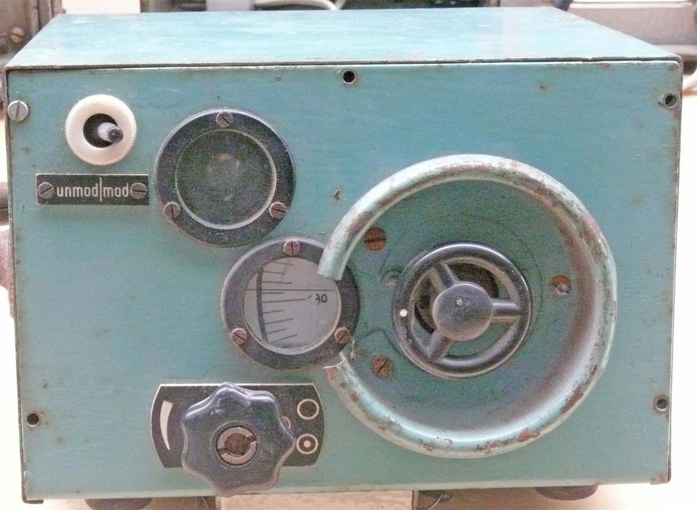
Photo 19 It consisted of a simple cavity wave meter, where the relative maximum value being indicated by means of a so-called 'magic eye' (right of the unmod/mod switch)
(our own collection)
We have already noticed, that Mammut, and we later will learn Wassermann as well, relied upon quite complicated compensators; though of different design. Where all antenna cables should be matched comprehensively.
For many decades this was accomplished by means of slotted lines. Though, how do these look like when quite low frequencies being concerned?
A slotted line should at least have a slot-length of > ½ λ; better is > full wavelength.
(ES2)

Photo 20 Not many will ever have seen such a long stretched slotted line. Its slot-length is 188 cm. The according wooden box counts even for 216 cm
(our own collection)

Photo 21 Typ ES 2
App. Nr. 288 03 (coded serial number)
bya is the general manufacture code for GEMA
(our own collection)
In Germany such a device is known as 'Messleitung'. I know, that the Telefunken slotted lines carried the code-name Lotus; whether this was also valid for GEMA products I don't know.
I cannot fully judge whether this device was being operated in conjunction to Mammut and/or Wassermann. For the latter, they might have operated one made by Siemens; because Siemens was its contractor.

Photo 22 The movable signal pick up
Text:
Achtung (attention)
Wagen nicht abnehmen (don't lift this box)
Vorsicht (be careful)
Federstift aus Glas (measuring probe is made of glass)
(our own collection)
For the latter device I estimate, that the (spring loaded?) glass rod touched the core of the coaxial system and had a silver deposited layer on it; though, not galvanic interconnecting it.

Photo 23 A choice of connectors should make this slotted line versatile
(our own collection)

Photo 24 For freaks, the slotted line core being mounted at some points only. We may therefore estimate, that v is behaving like it is kept within free air spacing (ε = 1) (Neglecting the v factor of the Cu conductor versus free space)
(our own collection)
Normal slotted lines do possess a measuring scale, which our device is lacking.
Intriguing?
Yes!
(4)
On 6 July 2015
Chapter 4
Please notice, that what follows might have got a new impact because an investigation done in the GAF Mammut bunker in The Hague has triggered a partially new understanding of what once might really have happened.
Date 28 September 2016
I would like to get into a rather unique document, which my friend Phil Judkins did find at NA (Kew), some days ago.

Reference 1b Copy of the front page of file A.D.I (science) report No. 1
(Crown Copyright, courtesy Phil Judkins)
Quoting from page 2
This report is a translation of a German official document captured by Royal Navy at the aircraft reporting station at Trogastel (?)* in Brittany. The equipment used similar radar components to the Freya, but has a large fixed broadside array. The direction of the beam is adjusted by means of an elaborate phaseshifter. Separate arrays and ganged phaseshifters are used for transmission and reception. The range of the station is 300 - 350 kms** on high flying aircraft and the D/F accuracy is of the order of ± ½° over the forward and rearward arcs of sweep of 100°. It is probable that the D/F accuracy would depend on the accuracy of tuning of the transmitter, the permissible tolerance being given as ± 0.1 Mc/s on the normal working frequency of 125 Mc/s.
The equipment seems to have been developed for the G.A.F. by the German Naval Signals Research Station at Pelzerhaken. It is stated that there are only 15 such equipments, later models being of different design and on other wavelengths, this implying that the small hoardings (FuMO 51, AOB) are also product of the same establishment.
Another captured document states that Mammut can be fitted with some kind of height finding attachment known as Malaye Gerät, but it is doubtful whether this is normal practice. The existence of a unit of this name is confirmed by the power supply connections shown in fig. 17, but nothing further is know about it at present.
* Rather often do suffer British wartime documents from very poor printed characters 'e', where hardly can be distinguished between an 'e' or an 'o'; only the merit of the text finally learns you what it likely should read.
** In these cases, you have to start from the lower range again (350 km measures then at 50 km). Distinction is possible, because the reflecting power of a rather nearby target is much bigger than it would have been at 350 km.
Let us concentrate first on the striking compensator unit
Quoting from page 3
Mammut
Introduction
The following description of Mammut search installations 1 to 15 presumes knowledge of the Dete (Freya) set, and therefore describes only the components differing from, or additional to, these of Freya. The Mammut consists basically of the units contained in the Freya cabin. Knowledge of the purpose, characteristics and operation of these units is therefore a necessary preliminary to a appreciation of the following report.
This description is accordingly designed as a handbook or instruction manual for the technicians, repair troops and engineers entrusted with maintenance of Mammut search installations. For the purpose of ordering of spare parts, a special manual has been published containing parts lists and diagrams showing constructional details. A list of parts for the main ranging unit (NB-Gerät) only is appended to this document. *
Mammut search installation after set 15 operate on other wavelengths and also differ in construction from the first 15 sets; these differences will be described in a supplementary handbook.
* Generally speaking, in the manual series dedicated to an apparatus or system, there always existed a list of parts descriptions. The Germans numbered every component, as well as used widely cable- or line numbers. When a cable interconnects several electrical points, then the same potential- or line numbering being used throughout. This makes servicing very convenient. It is not necessary to follow wires, but only viewing for equal line numbers.
Photo 13 The compensator type FK2
(with courtesy of Alain Chazette, from his above mentioned fantastic book)
However, on 3rd July I received very conclusive photos from Mike Dean. Who copied these about 1993 in America.
These show clearly, that we should drop the German NVK photo and should look at the next one

Photo 25 Viewing a very comprehensive example of the application of matching stubs
(111 SC 269029 - "US National Archives" courtesy Mike Dean)
It appeared that we possess such a "Stichleiting" in our collection

Photo 26 Stichleitung (GP/N) side view, similar to those shown at photo 23
(our collection)

Photo 27 Unscrewing the top-head: its most essential 'adjustable scale' setting arrangement becomes visible
(our collection)

Photo 28 The
German word 'stich' has something to do with 'stecken'*
(our collection)
We are viewing at the connector of such a 'Stichleitung', which should be plugged into one of the many connector sockets, each adjusted for accurate impedance matching.
This word might
originate from the German word 'Stecken'.
* Recently Heinz Trochellmann commented on this subject that it originates from 'stechen'
By the way, please notice the ceramic block, which constitute one the very accurate capacitor types used within a Messkette apparatus.
Let us now read again what the test on page 5 would like to believe us: It is debatable whether the open line slot constitutes 300 impedance

Reference 1c Section on page 5, dealing with the line impedance of the 'line-slot' shown in the photos 24 and 28
(Crown Copyright, courtesy Phil Judkins)

Photo 29 The slot core conductor is tubular. I doubt that this would have had a 300 Ω impedance, even when it would have been open at the opposite side too
(111 SC 269030 - "US National Archives" courtesy Mike Dean)
In the A.D.I. Report No. 1 they mention, equally to what I expected, that such a 'Stichleitung' should have had a length of ¼ λ. Though, when we look back at photo 26, we may estimate that the stub actually measures about 17 cm, which makes it about 1/14 th of the concerned wavelength (λ = 2.4 m).
I cannot yet judge what is inside this stub or 'Stichleitung', though, it could be also a series tuned device with some stub length incorporated. Maybe we should wobble it in due course.
We will about the final end of this Survey see that its behaviour is like an open coaxial line; where between 100 and 300 MHz there are no resonances present.
Photo 2 Showing the NVK NB module, which according this document should replace the regular GEMA NB dual display unit
(courtesy Alain Chazette, from his above mentioned fantastic book)
Do we have a mechanical reference to the measures to count with?
Yes, we do.
We know, that the CRTs in this module were of type HR 1/100/1,5; by the way, equal diameter to the HR 2/100/1,5 series.
This implies, that the screen diameter is 10 cm. Roughly measuring, we may estimate that the broadside of this NB module is double the screen diameter, thus about 20 cm.
Please look at the lower CRT screen again. We see signs of a burned-in vertical line. Yesterday, July 1st, I discussed with Jaap Keijzer, that it is curious that an optical projected line does apparently have similar deteriorating effects on the phosphorous layer as is having a static electronic beam. Jaap mentioned, that he himself had seen an optical lens of a heavy gun; where the pointer or cross or granule was illuminated for many years. Under particular circumstances, the granule was still visible in the lens (no longer mounted in a system). Nobody would believe him, but he said that it is true. Very peculiar.
Let us now focus on special aspects of the NB schematic based on the A.D.I. (Science) No.1 report again:
Drawing 13 There are minor, though interesting details
(courtesy Alain Chazette, from his above mentioned fantastic book)
Valve '94' apparently is a low power dual rectifier type RG 12D2, a diode for 2 mA current only. It should provide the negative 'fly back' voltage fed onto valve '80'.
To me of interest, is that the centre tap of transformer '95'. This is being fed symmetrically onto the the 'current source' valve '83' as to counter hum. Such kind of technique was quite common in sound amplifiers using direct heated filaments.
Maybe also of interest, is what operational distance they might have been counting with; considered from the theoretical optical range.

Drawing 14 Die optische Sichtweite in Abhängigkeit von der Flughöhe für die Aufstellungshöhe 40 m
NVK Funkversuchsstelle Pelzerhaken
(courtesy Alain Chazette, from his above mentioned fantastic book)
Let us consider the circumstance of a bomber stream. It regularly used 6000 m cruising altitude; in this case, the Mammut capture range was about 300 km.
Very helpful is the A.D.I. (Science) No1 report in respect to ultimate appreciation of the next schematic.
Drawing 8 Anschluss des Messzusatzes "+ 150" im Gerät Z 100
(courtesy Alain Chazette, from his above mentioned fantastic book)
Following the pointer mentioning NB-Gerät, I believed that this was extending the range of the NB unit.
This apparently is not the case.
Quoting page 10
C. The Range Measuring Attachment "+ 150".
A single switching arrangement which works with sufficient accuracy is used instead of additional units on the Messkette. The range is shifted by 150 km by turning the phase of the tone generator through 180°.
A double pole switch, situated within the reach of the operator, reverses the phase of the tone generator (Z-Gerät, Summer, AOB) voltage leading from the Z unit to the modulator unit. The voltage for producing the deflection voltage on the main ranging tube is tapped off after the switch; the phasing is therefore independent of the switch position because on changing over the switch the phase of the transmitter pulse remains unchanged in relation to the phase of the time deflection. On the other hand the transmitter pulses is shifted 180° in relation to the time-base deflection of the OB tube, which is independent of the switch position, so that 150 km must be added to the range reading on the "Messkette".
How did an actual operation room of a Mammut site look like?

(II)
Photo 30 Viewing the operation room of a Mammut F station at Blavandshuk Denmark (1945)
(111 SC 269017 - "US National Archives" courtesy Mike Dean)
My first impression: what a rather shabby outfit.
When this outfit would originate from the days when 'van Gogh' did paint his "potato eaters" in the 1880s - I would comment: poor people. There is nothing that reflects German 'wartime discipline' nor thoroughness.
About 15-17 January 2016 I discovered that the way the Steuersäule (steering column) is standing just attached of the lower control section of the N-Gerät front-panel. In particular in front of the display controls. This proves that the display- or presentation unit inside is of the special NVK type, and not of the regular type NB 110. Why? Because the NB 110 unit did have a goniometer-tuning accessible on its front panel. Not here existing.
However:
Viewing it from left to the right: The steering column; behind it the N-Gerät, we cannot judge whether it is being fit with the NVK NB display module, or with the regular Freya - Seetakt NB unit; a regular field telephone; The O-Gerät, consisting having on the left-hand side an OB CRT display and on the right-hand side the Messkette (OK Gerät) - fit with a mechanical-digital distance reading; the small box next to it, is likely the 'phase-shifting-switch '+150' for allowing range extension from 150 km up to 300 km; next to it the Z Gerät the Summer or time-base generator (500 Hz); on the far right-hand side the R-Gerät the medium- and high voltage power supply. Not to forget, most left of the N Gerät, we might see the wavemeter type FM 121, which previously being described. In the A.D.I. No. 1 report it is quoted - that frequency should be kept within a 100 kHz band limit accurately.
A practical query pops up in my mind, how did they service the N Gerät unit? Demounting the steering column first? Unlikely. For it they had to rearrange quite much.
Luckily we possess the genuine 1942 manual to Fu.M.G. (See takt) 40 G (gB)

Photo 31 Please compare yourself; isn't the equality striking?
(Fu.M.G. (See takt) 40G (gB)
The main difference between this photo and the forgoing, that the latter did have only 'claustrophobic' little room.
We are yet missing the T Gerät
The T Gerät (transmitter inclusive pulse modulator), might, however, be hidden underneath - just in between the two control wheels. Its regular cover being closed. To access it - in some way or another, the power control panel had to be moved away first.
(5a)
On 10 July 2015 + 16 July 2015
Continuing our "Entdeckungsreise" (Survey)
Chapter: 5ab
It should be noticed, that in the course of this Survey (eine Entdeckungsreise) several people have contributed; some of whom still being engaged.
Alain Chazette
Phil Judkins
Mike Dean
Dick van den Berg
David & Vincent Kossen
Without them - this Survey (Entdeckungsreise) would have never reached the point of knowledge and understanding where we actually stand.
Unbelievable!
Consequently, additional information forces me to adapt and changing some text passages again.
We got some days ago permission to duplicate a photo that appeared in Alian Chazette's supplement: Complément d'enquête en images; Alain Chazettes and Bernard Paich's nice booklet
Comparing photos - drawings as well as some contradictions caused by the text content within A.D.I. Report No1 of 13/11/44
Let us first start with:

Photo 32 According Alain Chazette's supplement book what is shown is the: .... face du radar Mammut F de Joubourg gîsant au sol après sa destruction en date 3 juillet 1944. On remarquera le détail des dipôles
(courtesy Alain Chazette, from the supplement to his above mentioned fantastic book)
The latter sentence is just what it says. We can have a rather close look at an antenna array which - regularly, due to its construction, does not allow viewing such kinds of construction details.
One matter is certain, it was a rather comprehensive antenna array.
It just popped up in my mind on 14 July:
Viewing the antenna related elements consisting of wires or rods - their stability seems to me quite delicate. Could it really stand heavy storms or gales, without deformation?
When Cu was used I highly doubt*; however, maybe they adopted a material that in wartime Germany became quite well known as Staku (Stahl Kupfer). Acronym for 'Steel Copper'; where copper (Cu) was galvanised (deposited) upon a Fe carrier. The thickness of Cu could be adapted onto its particular application.
* Another option could have been employing hardened (special treated) Cu
This material was used for many applications where robustness and, of course, the strategic material Cu could be saved (spared). We know, that skin-effect is forcing the high-frequency conductance towards the outer skin of metals at rising frequency; at very high frequencies one have to think of conductive layers of some microns only! Not always realised, skin-effect phenomenon is already measurable at our mains frequency of 50Hz. The higher the frequency - the more HF-conductivity is being hampered, in other words, encountering more HF-resistance thus loss. There exists a very interesting German wartime ZWB paper on this 'Staku' subject.
For example, this material was used throughout the Liechtenstein SN 2 (antenna) concept.
Considering this aspect, we should always bear this in mind.
However:
When we consider the above photo and look back at the next technical NVK drawing, you will recognise at least something.
Drawing 7 When you use your imagination, the similarities with the previous photo are quite striking. Comparing with the previous photo this drawing should be rotated virtually 90° anti-clockwise
(courtesy Alain Chazette, from his above mentioned fantastic book, slightly modified, AOB)
The U-shaped wires (lines) facing towards us, constitute two ¼ λ stubs; which do not radiate EM waves, but do provide 180° (signal) phase shift; here feeding the upper and lowest dipoles groups appropriately.
Let us consider how the
symmetric 300 Ω or 240
Ω line being matched onto the coaxial cable
arrangement. (The latter 240 Ω value might have been the case when the coaxial
cable impedance was 60 Ω, when a cable of 70 Ω was used it should have been 280
Ω generally- considered being 300 Ω, because these kind of 'baluns' do
constitute an impedance transformation of 1 : 4)

Drawing 15 Schema der Sperrtopf-Anschlüsse, für Mammut-Anlage ƒ 1 - 15
NVK Funkversuchstelle Pelzerhaken
(courtesy Alain Chazette, from his above mentioned fantastic book)
Please notice the heavy black dots drawn inside the (circular) Sperrtöpfe, these represent the connection onto the coaxial-cable-core; this ensures that the correct cable-phase being employed.
Please, notice also the date of this drawing concept: 12 February 1943.
What is most interesting - is the appearance of the actual 4 antenna quadrants involved. Also their numbering.
Sadly, the British report text
is not conclusive in respect to explaining the way such a Sperrtopf
functions. One thing is certain, that it should transform
asymmetric-line-currents into a symmetric-current v.v.; as well as an impedance
transformation in a ratio of 1 : 4.

Drawing 16 According Dick van den Berg - this kind of 'balun like' device is named Bazooka.
(source AOB)
On the 15th, thanks to David & Vincent Kossen, a photo of the remains of a Sperrtopf turned up! Which will be dealt with in due course.
In contrast to what I understood previously, it transforms impedances in a ratio of 1 : 1, though, symmetric into asymmetric v.v.
However, shown is my brief reconstruction of what is visualised in the previous drawing 15 about the interconnections onto these symmetry - asymmetry transformation devices, which the Germans designated: Sperrtöpfe
What becomes, nonetheless, apparent is that clearly the signal phase is crucial for proper operation, call it beam-forming; that is why there existed a comprehensive plan for arranging the correct (right) symmetric-line-phase onto each feeding point. However, I have probably drawn the screening cylinder inside the 'Topf' (pot) slightly too short, as I estimate it should also having a ¼ λ length.
Considering all together, it is apparent, that wide band operation is out off the question! Therefore the dipole elements are far too thin. This kind of 'balun transforming device' is too much responding (its accurate performance) onto a particular wavelength; hence, its mechanical measures.

Drawing 17 The place where 'Sperrtöpfe' were mounted (encircled in blue). For practical reason, the Sperrtopf being drawn at a single place only though, was implemented in between all places where a coaxial cable meets symmetrical antenna feeders
(courtesy Alain Chazette, from his above mentioned fantastic book, modified partly AOB)
For better understanding, I have not rotated this detail drawing, which is derived from the right-hand side of the Mammut antenna drawing 4
Please compare this drawing 17 with the side-view of photo 32; both are facing at the same antenna-plane.
According to A.D.I. No. 1 report, which is based upon a translation of a captured German manual - all coaxial cables should having equal length with a max. tolerance of 3 cm! I guess, including its coaxial connector.
I therefore believe: that all antenna cables being pre-fabed and a bunch of cables, including spare cables, being delivered by a manufacturer or institution (KM Ordnance?). Under field conditions, keeping tolerances (for a bunch of cables) up to the highest possible accuracy, might have been 'a bridge too far' for regular service personnel. It might even have been necessary, to use as much as possible cables originating from the same production lot.
Not clear to me, though likely, is, that at least two cable lengths might have been supplied, because, as we will learn below, the transmitter antenna section was nearer onto the compensator apparatus than was the upper receiving antenna array.
Let us follow some of the just referred onto text:


Reference 1d Some on the previously shown antenna details
(Crown Copyright, courtesy Phil Judkins)
More controversial is the following text as to how the compensator (Wellenschieber) does constitute.

Reference 1e Frankly speaking, I highly doubt this statement
(Crown Copyright, courtesy Phil Judkins)
Sometimes it is not always clear whether Allied personnel - editing German documents - do include their own vision or understanding how matters work; as was in a positive sense done in Radar News 19 (Funkmessnachrichten 19 issued on 25 February 1945). However, sometimes it causes confusion.
According the above text A.D.I. (science) No.1, we should understand that the core of the coaxial compensator device consisted of a solenoid.
Do we?
Photo 33 What is your opinion: is the coaxial core a solenoid?
By the way, please notice just up the rotating (arm) hinge spindle (pivot) - the coaxial four lines 'combiner'; there must, however, existed three more of these. Is the construction of such quite small combiner box possible in conjunction to the application of n x ½ λ coaxial cable lengths?
What just popped up in my mind: - the slot-line-boxes, in which's centre the coaxial compensator rail is mounted, is having quite solid housing-walls. Would this have been used for sound ground- or earth contact? Not unlikely, because such coaxial system need an appropriate ground contact! Hence, there is at once an extra sliding system involved for each slot.
Considering photo 33 carefully
Viewing the block like devices within the moving arm space connected onto the outgoing coaxial cables - must apparently have had side-wards sliding contacts, as to ensure proper earth or ground contact. (considering receiving application)
Translating the content of the just quoted reference 1e, it should electrically constitute a delay-line:

Drawing 18 My vision on a delay-line, in conjunction to the imaginable application of delay-line technique (reference 1e)
(AOB)
Though, is it valid in our case?
Let us take again a detailed look at the photo detail originally provided by Mike Dean

Photo 33a Who is having it right?
(111 SC 269030 - "US National Archives" courtesy Mike Dean, detail modified by AOB)
The core-contact-rail might even have been hollow - but doubtless it isn't a wound-up coil!
Looking at this photo carefully, we can see that the coaxial core rail is towards the centre being pushed a bit inwards; likely owing to the pressure of the sliding compensator-arm-contact. Far on the left-hand side the coaxial core apparently is not too often being pressed inwards (backwards).
After having dealt with this photo thoroughly, it is also found that the rear side of the slotted-line-sections were closed (screened off) (facing the transmitting compensator).
Matters becoming more strange:

Reference 1c Digesting the foregoing text-drawing and photos - someone must have understood according some text lines on '300 Ω line impedance' not entirely correct; maybe owing to technical understanding- or the translation of the German genuine text content or both stays open, yet
(Crown Copyright, courtesy Phil Judkins)
I would like to repeat, that when two soundly matched lines systems being interconnected - that at their mutual point the impedance becomes half value. In a system, were the SWR is 1, the system behaves fully ohmic. Hence, the above mentioned coaxial line matching behave like two parallel resistors. We all know, that two equal parallel resistors constitute: R/2. Let us consider, that both coaxial line impedances were 60 Ω we then have to count with 60/2 = 30 Ω. Might the editor have meant 30.0 Ω? We, likely, will never know.
We have to confront ourselves with the compensator next; maybe the German word: 'Wellenschieber' is more appropriate. 'Wellenschieber' may be translated in 'waves mover' (waves pusher). It, doubtless, moved wave-fronts.
I believe, that we have to look into the dimension of the compensator or, better, 'Wellenschieber' first.
When we deal with slotted lines, we deal with electrical wave responses; hence, between, for example, two nodes we deal with a phase difference of 180° (½ λ). This sounds more plausible to me than the 'fairytale' of a coil related delay-line!
Personally: I would like to express it frank:
NIX delay-line.
Schluss!
(5b)
The extension to chapter 5b
Date 16 July 2015
Continuing our Survey "Eine Entdeckungsreise"
What caught my attention - was the right-hand entrance-post (shape) to the Betriebsraum (radar room), shown in the next drawing. Possessing quite a number of books on bunkers, you hardly will encounter something comparable. Also the opposite wall shape viewed from the right-hand side bunker entrance; leading to what is designated Vorraum, is having a curious broadening. Please consider drawing 19 -19a.
Let us first consider the V 413 bunker floor layout

Drawing 19 The layout of the: KM Bunker Type V143
(Drawing copy made by AOB)
There are some shortcomings in this bunker drawing as, for example, the Maschienraum (generator room) does not have an entrance.
Going through Alain Chazette's wonderful book, I discovered a second V 143 bunker drawing, where the entrance to the operational room (Betriebsraum) has been drawn broader (wider). Maybe, initiated by the previous critical dimensions hampering the (compensator) trolley movements within the bunker-passage-way.
Let us consider whether it is possible to determine the maximum length (size) of the broadside of the 'Wellenschieber' (mounted on a compensator trolley)

Drawing 19a Scale exercise considering a compensator broadside (length) of 3 metres
(Drawing copy made by AOB)
How did I come to the actual measure shown?
Construction drawings regularly being made at a particular scale. When, for example, 5.00 metre been given, we may estimate that the length of this line is in a scale relation to 5 metres. I took after some preliminary trials - 0.6 x 5,00 = 3.00 metres. I first drew in my CorelDraw program a rectangular box, just fitting within the 5,00 meter room space called Betriebsraum. Afterwards, I reduced its length to 60%.
I duplicated the blue squares five times, and rotated them as to simulate the way the compensator frame has to be moved before it finally can be installed at its concrete base in the 'Kompensatorraum'.
By the way, on Wednesday 15th July I received a response from David Kossen on this latter aspect. He is a member of the Dutch bunker group of Wijk aan Zee, being in charge of the former V 143 Mammut bunker.
Quoting from his e-mail:
De door jou geconstateerde
afwijkingen in de deurposten aan de rechterkant van de bunker kloppen helemaal.
Via de rechterkant van de bunker werd inderdaad de apparatuur naar binnen
gebracht nadat de bunker gebouwd was.
Na het installeren van de apparatuur zijn de grote deurposten met metselwerk
verkleint, hetgeen vandaag de dag nog duidelijk te zien is.
What have we learned? We can prove since that the maximum module-length is ~ 3 metres (including its trolley).
Photo 33 Roughly calculated at the back of an envelope I used the third slot counted from the bottom
(111 SC 269030 - "US National Archives" courtesy Mike Dean, detail modified by AOB)
But, the first comparison trials were not very much conclusive.
Howerver:
Please look closely at the let-hand side of the Stichleitung left of the slotted section. What do we see? In my perception, the grey coaxial line going to the left-hand side has smaller dimension (its outer diameter) than is having the open slotted-rail section.
During re-measuring the size of the compensator slotted lines, when working on the upper line-slot, it appeared to me, that at the far right-hand side - just where the slot-rail ends - that there is a wire connected; instead of an expected heavier coaxial core.
Photo detail 33b Please look closely at the upper right-hand side of the slotted-line core
(111 SC 269030 - "US National Archives" courtesy Mike Dean, detail magnified by AOB)
The actual limiting photo resolution does not allow a shaper reproduction.
Hence, we cannot determine what the actual core dimension or shape inside the left- and right-hand coaxial lines were.
On the 11th, I measured accurately the various sizes of our Stichleitung device. I also used the opportunity to investigate whether our Stichleitung has galvanic conductance between coaxial pin and Al housing. This isn't the case. As to be sure that oxidation is not encountered, I changed the pre-setting number 15 to number 14*. There is still no sign of galvanic conductance. We may thus estimate, that it concerns a kind (capacitive) series tuned coaxial line; or a fixed capacitance and a variable tuned-stub-length.
* The way of scale numbering might imply that 'Stichleitung' adjustments might have been accomplished in 'steps' and not within a free adjustable range (within limits of course).
We don't possess a spectrum analyser, which would make life easier.
During the many experiments accomplished, I came up with the idea - that the genuine FK2 photo 13 was taken from the very centre front and that minor paralax-errors is to be expected; considering the lower slotted-line sections particularly.
Photo 13 This time I would like to use this genuine photo as to compare the size of the Stichleitung's removable cap (giving access to the tuning provision) - versus the length of some of the slotted-line sections
(courtesy Alain Chazette, from his above mentioned fantastic book)
Of course, we have to consider that some percentage of measurement errors have to be accepted. As we have to find an equilibrium between photo resolution at about pixel level and my personal judgement time and again.
I calculated, (relying upon a conversion factor of 17.575):
The third
slot from below is about 82 cm broad
The
lowest slot provides about 110 cm slot-(tuning)-length
Please notice at 9F what new information have brought to light.
We have, however, to notice, that for mechanical reason, the slot-length cannot be exploited fully.
Repeating, my sole reference is the accurate measures (sizes) of our genuine Stichleitung. Nowadays, a digital 'calliper rule' allow easy - accurate - measurements on devices. The combination and application of a computer drawing program, like our CorelDraw, is allowing rather precise comparison of measures.
(9F)
On 17 September 2015
We finally got a calibrated measure from one of the crew members (Hans Albers) of the Wijk aan Zee bunker group; who was so kind to provide the exact space (maybe with an error of a few mm only) between the two cog wheels axis shown below.

Photo 43 The exact space between the left-hand side cog wheel axis in front
and

Photo 42 At the right-hand side of the compensator room
Explained further down, both cog-wheels have been once linked by means of a kind bicycle chain. This chain had the function to guide the compensator arm for some deflection vwctor.

Drawing 36 The space between the two cog-wheel-axis (above represented by C and D, according the Wijk aan Zee Mammut bunker remains being: 2085 mm
In the foregoing chapter, I calculated for the lowest slotted-line length 110 cm. My previous calculation was relying upon the cap diameter of the Stichleitung we possess. This device is quite small and errors must be counted with.
According the new reference we get:
It is most likely that the lowest slotted line did have an actual slot width of 121 cm (space between E and F). I have to considered the entire slot-width - but have to notice some margin less, as the slotted-line-conductor ends about 1 cm less at either side.
Also interesting is the space between the points A and B; which is: 246,64 cm. This is the entire broadside length of the real compensator; though, the mounted frame is broader than visible on the integrated picture. I measured by means of a bunker drawing that the moveable compensator frame and chassis might not have exceeded 3.00 meter. This estimation does fit quite well to what just have been calculated.
Between L and K I did calculate 112 cm
We may roughly say - that my previous calculation of the measures of this compensator did have and error of 11 cm or, say, about 10%. I guess, not too bad after all.
Let us continue with the genuine text - which has been interrupted due to the forgoing new information
Please bear also in mind, that we deal here with a wave-length related device. The Mammut antenna arrangement is rather symmetrical. Therefore, the antenna phase centre (O°) is exactly at the mechanical centre of each slotted line section.
I would like to quote from Dick van den Berg's (Dutch language) recent e-mail:
Eens, de hele crux van de installatie zit in de “compensator”. Ondanks de gigantische afmetingen van de gehele antenne array kun je daarvoor met de goede kabellengtes de boel wel in de hand houden.
Bij een openingshoek van 2 x 50 graden, die regelmatig genoemd wordt, heb je maar een fasehoek van (Nx) ongeveer 140 graden nodig. Bij een golflengte van ongeveer 2,5 meter is dat minder dan 1 meter; met enkele aanpassing in een dielectricum (vanwege mechanische stabiliteit bij schuif/glij contacten) kom je dan op lengtes van ongeveer 70 cm. Als je naar de foto kijkt zou dat heel goed kunnen. De basis van het apparaat zou dan inderdaad in de orde van 3-5 meter worden. De draaihoek van de centrale arm en de nauwkeurigheid van de positionering plus aandrijving (het wiel op de console) past daar ook wel bij.
Het aanzicht met de hele bekabeling laat eigenlijk alleen maar zien dat er veel kabels zijn; de precieze routering kun je er niet aan zien, behalve dan de groepering in vier velden.
De bazooka’s zijn volgens mij gewoon 1:1 (dus alleen maar een balun). Er zijn steeds twee collineairs parallel. Als alles met “standaard” coax (60 Ohm?)werd gedaan blijft alles laagimpedant en heb je alleen nog maar een paar stukken met andere impedantie nodig. Je kunt een deel van die transformatie(s) wel weer onderbrengen in de compensator, evtl ook met de extra “stichleitungen”. In elk geval hoef je steeds minder “takken” samen te voegen en omdat de frequentie vast is kun je met “vaste” lengte kabeltransformatoren zowel de impedantie als fase “goed” blijven houden.
Please bear in mind, that matching errors can be minimized by adopting n x ½ λ cable length; the only downside of such technique, is, - that some transformation loss might occur. Its advantage may well prevailing the expected energy loss. I would not wonder, when this technique was, at least, accomplished for the compensator-arm-cables interconnected onto the combiners at the top-end of photo 33, as well.
Digesting all the foregoing bits and pieces, and studying time and again Alain Chazette's most interesting book I focussed my attention onto the following drawing again:
Drawing 4 Considering: German technical drawings are generally rather accurate, we may therefore quite well trust the way the antenna cables being laid (drawn)
(courtesy Alain Chazette, from his above mentioned fantastic book)
I was not yet aware of the implication to our Survey.
We may thus consider, that the lowest slotted line section is connected onto the most outside antenna sections; and the upper three slotted lines being connected onto the most central positioned dipole sections. The three top slotted-lines being of equal length.
From this drawing, we may also derive, that the lower transmitter antenna cables are having a shorter cable length than does have the receiving section. Please bear continuously in mind, that the slotted lines constitute a wave- or phase related transition-time-shifter. Consider for simplicity reason, that we deal with a transmitting signal - the essence is - that a signal arrives at equal time at both correlated antenna elements when the compensator being set in its mechanical centre (equilibrium).
When the compensator arm is moved out of the slotted-line centre, this makes the signal transport route shorter to the side in which it has been moved; consequently the opposite route becomes equally longer. Expressing it briefly: this latter signal phase being retarded and arrives some time-value later as the opposite side signal arrives earlier at the antenna elements. Time and distance being interconnected (linked) in the following equation: c = ƒ ● λ c = speed of EM waves, including light in free space = 3 108 m/s. In a transmission line (for example coaxial) signal speed might be considered between, say, ν = 0.6 - 0.9 dependant on which kind of dielectric being involved - 'c' has to be multiplied with a particular system parameter (called velocity factor). Though, it shows that the signal-(phase)-velocity inside a conductive system is always lower than the speed of light (in free space).
However, their centre-null is still being constituted by the mechanical centre null (0°) of the slotted line.
The three top slotted-lines being interconnected onto the central antenna section as is shown in the next reproduced schematic:
Drawing 15 We can clearly see, that the three central dipole groups (considered in the horizontal plane) are being feed in phase, whilst the more outer groups in an alternating phase sequence
(courtesy Alain Chazette, from his above mentioned fantastic book)
By the way, David Kossen did send us today (16th) some photos, among it some of a Sperrtopf remains, found some time ago, around the Wijk aan Zee Mammut bunker. Will be dealt with in the next extension of this very webpage.
However,
It becomes now more understandable - why and how - the compensator concept interacts with the design of the rather advanced antenna layout.
Beam-forming, maybe even suppressing unwanted side lobes might have been implemented in this general antenna system concept as well. But this estimation is still hypothetical - as long as we do lack proper theory or information.
Reconsidering the materials we got from Alain Chazette, I found a drawing which did not attract my attention before; though, might be to us crucial.

Drawing 20 Coaxial cable connections onto the compensator frame
(courtesy Alain Chazette, from his above mentioned fantastic book)
The numbers next to the slotted sections constitute the cable numbers onto the transmitting compensator. The most left- and right-hand side numbers (the outer ones) are concerning the receiver antenna (cable) numbers.
Comparing, both - this drawing 20 with drawing 15 (the previous drawing) it becomes clear that the given numbers do correlate fully to the antenna connections of drawing 15
(6a)
On 25 July 2015
We continue with:
Just the afternoon after completing our chapter 5ab, I found on our website two ZWB- Berichte, one on behalf of Prof. Zinke and the next one on behalf of Roder. Both dealing with Spreetöpfe
I consider the contribution on behalf of Roder in our concept the most promising, as it comes very close to the concept of the NVK Sperrtopf.
Sperrtöpfe


Drawing 21 Quite intriguing is the application of D and d
Derived from what is already on our website: ZWB- Berichte, please look for Roder's contribution
In coaxial techniques the ratio D : d determines the coaxial cable impedance, of course, also the applied dielectrics.
Seemingly the Sperrtopf impedance is in such a case determined by the inside diameter of the outside cylinder (D) and the outside cable screen (d). This is only valid for the case where it constitutes a ¼ λ.
Some weeks ago David Kossen did send us a bunch of photos, among it some of a device they once traced, probably using a 'metal detector', about the dunes surrounding their V143 Mammut bunker in Wijk aan Zee.

Photo 34 Shown is what the Wijk aan Zee bunker group dug out of the bunker surrounding dune
(courtesy David & Vincent Kossen)

Photo 35 The second picture of the same Sperrtopf device
(courtesy David & Vincent Kossen)
Our survey wouldn't be what it currently is without some additional curiosities and surprises

Photo 36 We are currently looking at the symmetric connections of the Sperrtopf device
(courtesy David & Vincent Kossen)
The outside cable screen will be dealt with hereafter

Photo 36a When we compare this enlarged photo detail with drawing 21 - as well as the symbolic Sperrtopf drawn in drawing 15, we must conclude that this picture is fully in accordance to what is visualized in drawing 15 and my perception is being expressed on drawing 16
(courtesy David & Vincent Kossen)
The Sperrtopf being discussed in Roder's ZWB paper differs a bit from where we are currently looking at.
Why?
Because in my perception, the circular ring is electrically interconnected onto the counter connection of the symmetric 60 Ω (antenna) connection.
We have to rely fully upon the data within the A.D.I. (science) Report No.1 of 1944, that the applied coaxial cable was Vacha type 726 (60Ω).
Not well visible is that at the top of the circular trapezium we notice the coaxial-cable-inner-core-connection.
Considering all this, we may assume that the outside metallic cylinder constituted an additional screening off provision.
The ceramic soldering techniques reached in wartime Germany world's best quality. We might even consider that it could resist all environmental conditions.
(6b)
On Sunday 26 July 2015
6b
This morning I received an e-mail from David Kossen, who pointed that I did not always write his name correctly; this omission has been instantly corrected.
He did also send me an interesting hyperlink (will be given further down)
By the way, following this photo series - these was not taken within a (KM) V143 bunker, but from an early, perhaps the first GAF (Luftwaffe) Mammut bunker, about 1.5 - 2.0 km north of the other Kijkduin bunker; near to the Kwartellaan (The Hague NL). This latter reference was told to me by Tim de Mos, when he guided us during a temporarily 'open bunker day' held in September 2014.

Photo 37 We discussed the way the slotted coaxial line being interconnected onto the coaxial-slot-ground
Voilà, my estimation was correct, although, I did not have a perception how they accomplished it in detail!
(copied from www.haagsebunkerploeg.nl)

Photo 38 Viewing the plug-base for the Stichleitung device. Please notice in the background the transmitter compensator lines
(copied from www.haagsebunkerploeg.nl)
What can we learn from this photo?

Photo 33b Please look at the upper right-hand side of the slotted line section, we can just see that an approximately 2 à 2.5 mm2 wire runs into the coaxial tube. The coaxial section about the Stichleitung socket is just having a bit smaller diameter (hence, a higher line-impedance) as is having the further outwards going coaxial tube. (outgoing is only what we see, as in a matter of fact the antenna signal goes into the slotted-line section)
Considering the line dimensions, we may assume, that the line impedance just where the Stichleitung is attached is a bit different from the: left- and rightwards facing coaxial lines.

Photo 39 We may assume, that the coaxial line-tube-ends were being fit (soldered) within the tube-mouth. This, in my perception, because otherwise their mechanical stability could not have been sufficient rigid. Please notice, that the system on the left-hand-side belonged to the transmission system; whilst the receiving section is on the right-hand side
(copied from www.haagsebunkerploeg.nl)
Please view the way the slotted line-ends were mechanically coupled onto the outward facing coaxial systems; simply by means of 3 or 4 mm slot-screws.

Photo 40 Maybe of interest is also the gearing system that was, most likely, used for moving the compensator-arm-position.
(copied from www.haagsebunkerploeg.nl)
When we look carefully, we might see, that the gear-system was driven by means of a shaft and that its motion being 'brought-over' onto a chain provision.
Comparing this current position with the drawings 3 + 5 as well as photo 30, we may assume that on the right-hand side we have the transmission compensator side (section) and of the left-hand side the receiving compensator arrangement.

Photo 41 I don't know yet where this gear wheel is mounted; I would, however, not wonder that it had to move the compensator-arm at its lower side. A chain is a convenient means moving such a device, like an arm steadily - forward- and backward
(copied from www.haagsebunkerploeg.nl)
Another option, it might have been mounted at the compensator-arm-spindle (at the top), but this would have demanded quite some moving energy. I therefore opt for a moving provision attached at the end of the compensator arm near to the lowest section of its mounting frame.
(III)
On 19 January 2016
In a discussion with Bas van den Born today, a photo-drawing compilation was looked for and not found.
I don't know why, but it ultimately was found in a stored file kept on the HDD which I have brought with me during my holiday time abroad.

Explaining what was initiated when a compensator arm being moved
(111 SC 269030 - "US National Archives" courtesy Mike Dean, explaining its principle by AOB)
Please bear in mind, that the virtual beam swing was projected always perpendicular onto the compensator-arm direction. By moving the compensator arm the Mammut antenna radiation beam was also rotated between left - 50 - 0 and to the right +50 degrees.
This information fits perfectly to Dick van den Berg's next theoretical explanation.
(7-DvdB)
In the meantime, we received a desperately awaited contribution on behalf of Dick van den Berg
His contribution has been add:
On 2 August 2015
7-DvdB
Quoting Dick van den Berg
The Mammut Phased Array
Introduction
First, all WW2 radar and direction finding equipment needs high gain and directivity either in beam elevation azimuth or both. For airborne systems use of microwaves in L, S, C, and X band is most really mandatory. Allied H2S and H2X were far superior in relation to most German flight radar. Ground radar however which needs also greater detection distances may use longer wavelengths almost equal pulse power and hence rather massive aerial systems. E. g. the British Chain Home early warning radar used a frequency around 25 MHz and towers up to 120 m high in between the curtain antennas some 120 meters long were hung floodlighting the space in front. Due to there physical parameters the system was not quit accurate though successful. Leaving German Wurzburg all their other LW en KM ground based warning radar used frequencies in the VHF spectrum say around 120 MHz. Realizing pencil like beams needs large and more or less complex –electrically and mechanically - areal systems. Height finders like the Wasserman towers almost 40 m high weighting some 50 tons with their 360 degrees azimuth coverage had to be spun every 10 seconds. In a way a static electronically steered beam can be a major advantage especially in early warning systems spotting relatively slow and heavy aircraft.
In an almost last tour de force German engineers developed Mammut. Wanting an unsurpassed precision of 2000 m at 300 km they needed a beam width of 0.5 degrees combined with an substantial erp pulse power based on electronics that could fulfil the basic power pulse shape and repetition rate. The output of some arithmetics based on back then also known formulae showed the basic demands. Tube electronics could provide up to 20 kW pulse power. What was needed an antenna array that could pinpoint the narrow beam without sidelobes within 0.5 degrees thus merging enough gain. Using simple antenna elements the answer was a reflecting mesh with each 24 collinear radiators in a rectangle 16 x 24 m including also an equivalent receiving system in front off it. Sometimes even all this was doubled at the backside. One decided steering azimuth only. Maximum angle 100 degrees (leaving blind angles 2 x 80 degrees along the main construction). The vertical beam angle determined by a fixed and invariable element configuration only. The system resembles the earlier and far most used Freya radar. Essentially there’s antennasystem was duplicated. With Wassermann the elements were vertically aligned giving an (rotating) height finder. Mammut used the elements horizontally multiplied to give a horizontal beam 0.5 degrees wide. The mechanical complex and heavy rotating tables were omitted and replaced by electronic constant phase difference steering.
Antenna Arrays
Narrowing beam aperture without introducing side lobes can be done favourable using simple elements in a smart spatial array, i.e. to make an assembly with the proper electrical and dimensional configuration. The total field of an array is a vector superposition of the fields radiated by each individual element by constructive interference. To control the radiation pattern the designer chooses from the geometrical configuration, the relative placement of individual elements, the excitation of each of the elements with amplitude and phase. Using (vector) electromagnetic wave theory is a tedious task. In the following survey only some outcomes will be used. Maybe expected: most theory can be reduced to some general conclusions. An (ideal) linear array (as this Mammut hoarding array) can be described as one equivalent standard element in the origin times an array factor dependent on geometry and phase increment.
The Mammut Array
What would be some minimum demands? Using the ideal (without extra losses) radar equation estimating receiver sensibility and the radar cross section of airplanes one can see that a detection range of 400 km is almost impossible; 300 km is viable but overall gain of the aerial calculates around 30 dB (assuming 50 uV at the receiver at 125 MHz). These figures dictate the rather formidable dimensions of the array. GEMA (NVK, AOB) engineers choose for a 31/2 lambda phased vertical collinear giving some vertical plane gain and beam narrowing. All elements are located one quarter lambda in front of a mesh isolated thus with quarter wave lambda stubs. Phasing is done by quarter wave lambda closed stub also (with their own isolated studs). These configurations are center fed by open line connected to a bazooka (spertopff) and then to the coaxial lines. These lines are estimated to be less then 70 Ohms (the dielectricum is not yet know; the impedance could simply be standard Vacha cable between 30 and 60 Ohms). The total receiving and transmitting aerial are mirror symmetric around a vertical trough the center. The complete top section (24 elements) is for receiving, the lower sections (24 elements) are for transmitting. All cables lead to the phasing and electronic apparatus down in a concrete shelter.
Left diagrams and (scarce) documentation shows how the station was build. There is a strong suggestion of the overall symmetry in the aerial and cable layout. It is a pity that only scaling and estimated guesses can reveal details. Almost all hardware is gone or strongly affected and corroded. With difficulty one spertopff could be used for measurements and a stichleitung will be measured in due time. All this “compulsive hoarding” resembles Antonioni’s picture “Blow Up”. The picture that might hide something doesn’t reveal more when blown up. The details become even more puzzling.

Figure 1 shows a few theoretical and mathematical elements regarding arrays. Figure 2 sketches part of the Mammut antenna. One sees the constant phase difference wich can also be stated as delayed time. The signal of a wave from element 2 needs tot be delayed be a time depended on x1 in figure 1. The same wavefront will then induce an in phase signal in element 1. The same with different delays hold for every other two element. In the end all signal can be summed in phase. Only signals from direction angel theta (θ) add in phase. For every different angle there exists a different but steady delay time. For symmetry reasons a delay may be divided in after and ahead as long as they sum up correctly.

Figure 3 represents the compensator schematic. Mind also the symmetry. In order to take care for unwanted phase and time faults all cables are well designed at special lengths. Figure 4 is a drawing (not to scale) of the compensator. All sorts of considerations led to a base length around 3 meters. One can estimate the various lengths of the slotted lines with the movable contacts. Of course there must be enough length to introduce the correct phase/delay. The instrument has to be quit sturdy and exactly to fractions of centimeters. A complicating factor arises when the pivoting arm moves. There is a movement in two directions and there has to be always a solid contact between the center conductor as well as the outer of the line ( transmitting 12 kW pulses gives 800V plus and 14 Amps).
The most oblique radiation angle is given as 40-50 degrees. With an element spacing of ½ lambda at 125 MHz the maximum first (and later constant multiples) phase angle is delphi ≈ 0,35 i.e.± 70 cm. This would also be the maximum length of the first (top) slotted line. However we see that in real the three top rows are substantial shorter. How come? Is there a dilelectricum used? The lower rows ample meet the minimum constraint in length.
Looking at the compensator one sees a practical j(y)oke. The contact arm divides each base Ni,i+1 in portions depending on a tanθ function. The left side is diminished while the right side is augmented with an equal part. This equals the demanded delays for each of the paired elements. The relation between the two θ’s (beam and armdrive) is a cosine. The steering is not a linear one. The driving of the wheel and the indicator can compensate for the difference. In order to get the exactly needed phases everywhere it is absolute required to contact the compensator and each antenna element as well as the combiners with a cable with the very right length. Impedance and phase matching may be done to some extent with the stichleitungen. It is not excluded that somewhere transmissionline transformers were used. The precise role of the phasing baluns in relation with the overall antenna diagram (and overall (cable) phasing) is also not clear yet (mind you: the six central ones are equally phased, all the other are shifted one group to another). How the impedance matching (there are various combiners and different length cables for interconnections) is done is not yet clear. Latest pictures reveal that a square slotted line was used (which of course is no problem). More to be resolved!
(7-WaZ)
On 3 + 10 August 2015
Time was found today to dedicate attention onto a photo series made, on my demand, by David & Vincent Kossen.
This time I thought to show coaxial cable details found in the V 143 Mammut bunker of Wijk aan Zee. We will see, that matters moved a bit differently, as David & Vincent took also photos of the compensator-base-remains inside their bunker; of which existence I wasn't aware off when we visited the bunker in Wijk aan Zee, last May.
We will experience today another occasion - that carefully viewing at pictures can learn us a lot!
Photo 42 Photo apparently taken from the right-hand side of the compensator concrete base. Please, bear in mind, that the photographer stood with his back towards outside bunker wall
(Courtesy of David & Vincent Kossen)
When you look carefully, you will see that this gear system has some in common to the situation shown in photo 40 shown next.
Photo 40 When you compare this photo with the previous photo 42 it is clear that there exists some similarity, but not entirely. The reason might have been, that this photo was taken from an early GAF Mammut type and our photo 42 shows the KM V 143 bunker outfit (what remained of it)
(copied from www.haagsebunkerploeg.nl)
Photo 42 Again. Intriguing me is the short shaft (rod) facing towards us. Apparently the remains of a kind of flexible coupler hanging in the air
(Courtesy of David & Vincent Kossen)
Just popping up in my mind - wherefore was meant the box left of the gear-wheel section? Please notice the the screw on top of it; apparently to be adjusted in some way. It might have been a driving gear box, powered from the operator room.
I have to ask David for an additional photo, taken from opposite.
We are viewing it from the rear-side of the bunker compartment, and the real driving system might have been provided from the opposite side; thus from the radar operation room. My hypothesis, is, that it might have once been connected onto a kind of servo-repeater (Drehfeldgeber), showing the actual compensator-arm-deflection vector. Why? Because I believe: - that such kind of coupling is not made for stronger forces; and the radar-operator was both controlling the actual bearing - as well as watching the overall radar range (in that particular antenna-beam-sector). One of their operational parameters was - what is, among distance, the actual bearing vector precisely?
A personal visit to the bunker on Saturday 8 August, I learned that my understanding of the driving mechanism should be thought rotated for 180 degrees.

Photo 42a The wall in the background is the real wall of the bunker. The dead shaft-end is facing into the direction of the radar operator room
(AOB)
However, David and I discovered that extending virtually the driving shaft into the direction of the operator room, that there is a brick wall to pass. There must have been an indirect means rotating it. Whether mechanically or electrically - or even a combination of both - stays open yet.
The u-shape holder on the right-hand side was to fix a cable-holder frame. This latter provision was important as to relieve mechanical force (tension) onto the compensator construction. It was also keeping the coaxial cables in place just where the cable connectors meet the far outer ends of the compensator lines.
In my previous chapter on the Kwartellaan bunker photo series, I supposed that the compensator-arm being most likely fed near the compensator base.
Photo 43 What we clearly can see is the chain-gear opposite the driving-mechanism-side. The rear room wall is on the left-hand side, and the operator room-section was on the right-hand side
(Courtesy of David & Vincent Kossen)
When you look carefully - at the output-side of the driving mechanism opposite, you can see a hole, which most likely is meant for the lower side of the chain-belt (movement). (when this word is appropriate fitting to this situation)

Photo 44 The coaxial cables in the background being mashed up
(Courtesy of David & Vincent Kossen)
In the background the right-hand side of the compensator room section.

Photo 45 I guess, David (or is it Vincent?) is looking for cable details. Viewing the left-hand compensator side. Cables running to or from left-hand side bunker pedestal. At the top of the bunker cables being cut-off. Please notice, that originally there ran 24 coaxial cables - of which 12 for the receiving- and 12 for the transmission system
(Courtesy of David & Vincent Kossen)
The three concrete pedestals had been removed - as to equalise the bunker roof in post war days. Please notice the steel-pleated sealing. This was standard German bunker technique. The reason, when for what ever reason a bomb- or grenade-shell penetrates the - at least 2 m thick - bunker roof, often its penetrating power being not sufficient enough and being effectively hampered by these kind of steel plates. May be deforming it a bit, though, often protecting against a blast.

Photo 46 I do not entire understand what we are looking at
(Courtesy of David & Vincent Kossen)
More details can be find in section 8b, below.
On the other hand, according A.D.I (science) Report No 1 of 1944, Vacha 726 coaxial cable of 60 Ω being used; this implies a rather thick coaxial cable core.
It might be a core consisting over several twisted cores, though, at, say, 125 MHz an unconventional technique. On the other hand - compare this one with the next photo

Photo 47 This 'calliper rule' shows a core diameter of 1.5 mm, quite unlikely for such an application. Roughly, it would make the ratio of D : d in respect to an cable impedance of 60 Ω most unlikely!
(Courtesy of David & Vincent Kossen)
Hence, we might think of a thicker coaxial cable core; whether consisting of multi-cores I cannot yet say.
Our today's conclusion: - we have likely found the way the compensator-arm was once had been driven. It was being moved from the lower section of the compensator-arm (when one stands in front of it).
The coaxial cable measures not being regarded conclusive yet, but we might have come nearer to a final conclusion.
(7-WaZ-2)
On 4 August 2015
Yesterday evening we received a next bunch of photos and some documents on behalf of David & Vincent Kossen.
David and his brother Vincent are both dedicated members of the Wijk aan Zee 'Atlantic Wall' preservation group. Like the group in The Hague (and elsewhere), they are mostly quite young men - dedicated to the preservation of the historical past; particularly in respect to their local wartime context. However, still placing (guiding) it in a serious overall wartime frame*. Not playing (costumed) wartime like games! The historical building remains were often being covered, for many decades, under sand or where being made inaccessible in various ways. Not always noticed, is, that in some way or another, from all the (mostly) concrete fortification (shelters etc.) built in the Netherlands during German wartime occupation, still 36 % did survive - according to Hans Sakker's and Rudi Rolf's 'bunker bible': Duitse bunkers in Nederland, of 2005; quoting from a summary at page 59.
* Since the fall of the iron curtain in 1989, the opinion on wartime history did change quite much. In the course of the 1990s it was also by officials understood that even wartime fortifications being part of our recent history. As it did have such a huge impact on Dutch human lives. As an example - The Hague did likely the first step in recognising - that the many remains of their traumatic past, still plays a role in their current days. In the early years of the new millennium, groups were formed and got peu à peu permission to take car of some wartime defence monuments. These being considered a 'Heritage, though, without the obligation of conservation'. This legal status make matters more simple to accomplish. Quite some of these private initiatives also contribute to tourism. And - tourism is important to local business. Don't consider this as an easy undertaken. For example, it can happen that electricity should be applied for. New underground cabling being laid; sometimes costing between 10,000 and 20,000 Euros. For amateurs quite some smart funding have to be find. I know from the bunker group taking care of the two bunker on the Badhuisweg in Scheveningen, that they needed to install dehumidifiers. Everybody acquainted to these techniques know, that these apparatus have to run nearly continuously; someone have to pay the charges; seemingly, they can manage.
Returning to our objectives again.
I would like to start with some reproductions.

Photo 48 Postcard showing peaceful Wijk aan Zee, Van Ogtropweg. I guess of 1945/46 maybe 1947. On top of the dune the remains of a (KM) FuMO 214 (Naval Würzburg Riese - Giant Wurzburg version)
(Courtesy of David & Vincent Kossen)
In those days Wijk aan Zee was a small village, laying just behind the dunes.
Together with my mother, I spent an 'one month' vacation in Wijk aan Zee, in the summer of 1948. She rented two rooms attached to Bakkerij Ledder's shop (I still remember vividly their dark blue painted kitchen, a sticky fly-catcher hanging from the sealing). With the son of the bakery owner (Mr Ledder), I made quite some explorer tours through the dunes (he might have been about 8 to 10 years older than me). I cannot remember having seen any antennae. All accessible bunkers were then (already) empty. The story was told, that only the 'Red Cross' bunkers should remain - the rest blown up; which over seeing the current situation, wasn't to happen.

Photo 49 Wijk aan Zee Panorama. Viewing from left to right the following radars: Mammut on top of the V 143 bunker type; probably a Seetakt radar, otherwise a Freya set; Würzburg Riese (Giant Wurzburg), likely (KM) type FuMO 214
(Courtesy of David & Vincent Kossen)
Peaceful Wijk aan Zee, a rather idyllic scene. I guess, that this photo might have been taken in 1945/46, though before 1948.
Please notice the circular bunker-head, which was once an observation post; still existing. Albeit, that it belongs now to a recently obtained private property, being not accessible yet (status end of May 2015).

Photo 50 The (KM) Mammut antenna mounted by three pylons on top of three concrete pedestals. Please notice the two long-stretched (service) balconies at the rear side of the antenna mattress frame. Notice also the (rain?) covering roofs. There also exists a top rail which likely allows servicing of the antenna front section. Also of interest is on the far right-hand side the parabolic antenna dish of a Renner I radar apparatus
(Courtesy of David & Vincent Kossen and Photoshop work on behalf of my wife Karin)
The 'Renner I' radar apparatus was a (1944) modification of a regular Seetakt apparatus. The transmitter (including pulse modulator, timing* and IF modules) and receiver front-end were removed and were replaced by Berlin FuG 224 modules. To what I understand, most of the remaining equipment was still more or less standard GEMA technique. Hence, range reading and bearing taking were relying upon conventional techniques. The purpose of accomplishing it this way, was to convert the system from the decimetre spectrum of λ = 80 cm to the λ = 9 cm wave band (S-Band), with minimal use of time and materials. Basically, the FuG 224 techniques were derived from captured British H2S techniques, discovered on 3rd February 1943. Catching-up was an enormous task organised on behalf of the AGR Committee; they actually never really could catch up, as their war situation deteriorated so rapid that finally only a few systems were becoming operational in early months of 1945. Think of not yet 150 systems - for both KM and GAF + training etc. altogether; peanuts!
* Timing might still have been derived from the regular GEMA Z module, and range reading from the 'O' module)
However, the three concrete pedestals being removed since. Nevertheless, the shown bunker entrance is still being operated by the Wijk aan Zee bunker guys. The previously shown photo series (42 - 47) were taken inside this very bunker.

Photo 51 Renner I radar installation fit for 9 cm operation. Shown is a magnified selection of the far right-hand side of the previous photo
(Courtesy of David & Vincent Kossen)
The antenna dish looking (facing) land-inwards

Photo 52 On the left-hand side the still existing observation bunker. More to the right a Seetakt (Freya?) apparatus; and at the far right-hand side a WB-Riese likely of KM type FuMO 214 - its parabolic mirror actually being dismantled half way
(Courtesy of David & Vincent Kossen)
Considering all foregoing photos, we may assume that some reshuffling have been taken place in the meantime; as some systems do not appear at other photos.
I consider, that it is most likely that this sector being controlled by the KM and that therefore their systems being engaged.

Photo 53 This
photo was taken from the command bunker. Still existing, albeit,
invisible because the 'Hotel Hoge Duin' (Wijk aan Zee) being build on top of it.
However, in last May we could kindly visit some sections of this very bunker
complex; only a few hundred metres away from the V 143 Mammut bunker. The light
reflections might originate from the photo reproduction
Photo 53 Afterwards David Kossen pointed: that this bunker did not concern the command bunker - this object is visible on the far right-hand side, though, it was taken from the nearby FLAK bunker. And, that the tube construction belonged to a former camouflage tent.
(Courtesy of David & Vincent Kossen)
Please notice, that only the base of the former FuMO 214 remained.
(7-WaZ-3)
On 5 August 2015
I just received an additional photo of the once captured 'Renner I' radar apparatus.

Photo 54 David & Vincent Kossen provided a better 'Renner I' picture
(Courtesy of David & Vincent Kossen)
However, together with his e-mails he did send me 5 photos which really knocked me down!
The following report proved to be at the end invalid.
I therefore, have to correct some of my estimations

Photo 55 Where are we looking at?
(Courtesy of David & Vincent Kossen)
He did strip a few cms of a very deteriorated coaxial cable-end of what once should have been Vacha 726 cable type.

Photo 56 We apparently are looking at the outer skin of a coaxial cable - really?
(Courtesy of David & Vincent Kossen)

Photo 57 The coaxial cable determined further
(Courtesy of David & Vincent Kossen)

Photo 58 Viewing at what I believe is the inner coaxial cable
(Courtesy of David & Vincent Kossen)
Its black coloured dielectricum
compound might have been made of Oppanol, an IG Farben product. The
long-stretched beads might have been made of Mipolam, a well known IG Farben
product.

Photo 59 The most outer cable screen. Just visible a sticky foam; in between of the (centring) beads and the outer copper screen.
(Courtesy of David & Vincent Kossen)
The next e-mail conversation David was pointing at the fact - the central core is behaving magnetically!
What?
His thought was - that the centre core was only implemented for cable strengthening.
Is this possible?
Yes and no.
When its properties are truly
responding magnetically, it might concern Staku material, discussed previously
in regard to the material where the antenna-rod might have been made of.
There exists a very interesting German wartime
ZWB paper on
this 'Staku' subject.
In my perception it is most unlikely - that the centre
core of a coaxial cable isn't electrically part of the energy transporting
medium.
Drawing 15 In my perception,
the inner coaxial cable might fit quite well onto (into) the Sperrtopf provision
shown on this drawing
(courtesy Alain Chazette, from his above mentioned fantastic book)
On the other hand, the real coaxial cable (line) is having a quite small diameter.
Completing my perception, the outer screen
being used as to screening off from environment. Such a conductive screen is
then often connected onto ground at a particularly determined single point. I
think, the best point in this application would have been the coaxial connectors
left and right of the central compensator system.
Screening off is rather important, as it might happen that next to the Mammut system does operate a Freya apparatus operating at the same frequency band.
When the outside cable screen would have been part of
the energy transmission, it would certainly pick up some energy from its
surrounding. When the outer screen isn't part of the signal transport, it
cannot convey outside induced signals (at least not electrically).
Hypothetical?
I don't think so!
Who knows it better?
Please come forward!
Our e-mail address can be found at the end of this webpage.
On Saturday we would like to visit the 'Wijk aan Zee bunker group'. In particular - I would like to see myself how the remaining compensator-arm gears must have operated. But now also seeing what this cable section is about.
Not long after having put this on the web, I did receive David's next message:
Gebroken kabel voor de sperrtopf
verwijderd en de boel doorgemeten.
Restultaat:
- Kern lijkt te zijn aangesloten op het "knobbeltje" maar ik meet waarde's
tussen de 2 en 16 Mega Ohm?
- binnenste afscherming is aangesloten op het knobbeltje en ik meet 0.16 Ohm.
- Buitenste afscherming is aangesloten op de behuizing van de topf en de ring
onderop de topf, ook 0.16 Ohm weerstand.
David pointed:
Having disconnected the broken cable attached onto the Sperrtopf
Results:
Seemingly, the centre core being interconnected onto the what we designate 'bump' (bultje) though, he measures a resistance between core and the solder on top of the bump - 2 to 16 MΩ, thus an open connection
Between the outer copper screen of the inner copper screen and the bump: 0.16 Ω (The helical like small copper tube)
Between the cable outer copper screen and the outer screen of the Sperrtopf, as well as circular ring on top of the ceramic Sperrtopf top: 0.16 Ω
There hardly can be another conclusion than that - what I regarded being most unlikely - is just right. My hypothesis being not valid
One is never too old to learn from an invalid judgement!
(8)
Already long on my agenda
Chapter 8
On 6 August 2015
About dead zones
The radiation pattern of an antenna is quite easy to predict as long as it concerns a single ½ wave (wire) dipole > ⅛ λ above perfect conducting ground.

Drawing 22 The radiation pattern of the above described ½ wave dipole ⅛ λ above a perfectly conducting surface
Please notice, that at all points at the dotted line signal strength is having an equal value. It seems that this radiation pattern is horizontal being polarized, but you can rotate this diagram around the dipole-wire-axis at will and the radiation pattern stays the same; as long as the height above ground is > ⅛ λ*. In this latter case, when the surface allows reflection will occur and the radiation pattern vertically will benefit from the directly upwards directed EM field added with the ground reflection
(AOB)
* When the dipole is being moved further upwards (height increasing), the vertical antenna pattern (shape) will become more flattened and might also getting side lobes.
Matters become worse when several antennae elements become involved.
For this occasion I would like to rely on a GAF antenna course syllabus [1]:
Flugmeldedienst
Heft 9
Einsatz für Funkmeßgeräte (radar operation)
March 1944
They refer mainly to Freya like systems, as this was the backbone of the GAF early warning service.
Luckily to us, the Mammut antenna array constituted actually an extended version of a Freya antenna system.

Drawing 23 Let us first consider the positive situation, where both the direct- and ground reflected wave do add to one another (summation)
[1]

Drawing 24 This time the downside of signal summation. Wave 1 constitutes the regular radar signal, but the reflected wave 2 just arrives at a point where both waves do differ 180° in signal phase. The mathematical result is that we will detect - less or even no signal-strength at all (substraction)
[1]
Hence, it will be temporarily constitute a dead area zone; when the aircraft continues its flying path it will appear on the operators radar screen again. When - is determined by various parameters, such as - its height, but also the antenna radiation pattern as well as its relative altitude above ground or sea-level etc.

Drawing 25 Considering a more theoretical approach, without bringing the proof
[1]
Some of you might remember these kind of analytic geometry problems from their school days.

Drawing 26 The cause of dead zones (Auffächerung und toten Zonen or Nullstellen), taken the regular Freya set as an example (say, λ = 2.4 m, 125 Mhz)
[1]
Quoting [1] page 21:
Die Zahl der Diagrammlappen (number of lobes) in Abhänigkeit von der Aufstellungshöhe (relative height of a system)
Die Zahl der Finger (lobe numbers), in die das Strahlungsfeld aufgefächert wird, hängt von der Höhe des Sendespiegelmittelpunktes über der Reflektionsfläche ab
Numbers of lobes = Antenna-centre height x λ / ½ λ

Drawing 26a Explaining one out of the many causes that will generate vertical radiation lobes
[1]
Using the example figures given in this drawing, and using the just mentioned equation, we get:
Considering Freya's standard wave length of 2.4 m
A = 3 x ½ λ / ½ λ → providing 3 lobes

Drawing 27 About the creation of active- and dead zones correlated to the location height of a radar antenna
[1]
However, you might getting the idea that only ground reflections are causing dead zones, but this isn't the case. Because, the various radiated EM field components in the near-field of an antenna array, will also causing irregular radiation pattern zones in the horizonta; plane. The Germans use for it the word Auffächerung. Though, this time we will neglect the aspect of horizontal (beam) lobe forming.

Drawing 28 Showing what the detection limits are owing to the curvature of the earth
[1]

Drawing 29 However, practically the operational range is reaching farther, because of EM wave refraction. Such phenomenon can also be observed, when EM waves just do touch a rim or mountain
[1]

Drawing 30 Optical range and extended range due to refraction. This German document called it 'Erfahrungswert' or - derived from experience
[1]

Drawing 31 Another nuisance or downside is scattering - due to clouds at various altitudes. Quite likely above the North Sea and the Atlantic environment, most time of the year
[1]

Drawing 32 Reflection range of two aircraft types (Me 109 and Hs 126) range versus altitude as well as lobe forming
On 10 + 11 August 2015
Visiting the Wijk aan Zee Mammut bunker again last Saturday; we got from David Kossen a neatly prepared Vacha 726 type cable end - as a gift to our collection.
My friend Phil Judkins did send me in the meantime a copy of a British wartime - RAE (Farnborough) report on German coaxial cables.

Photo 60 RAE Radio Department, No. RAD 250, February 1945
Radio S.5132/RCM/29
21st December 1944
(NA/GB, AVIA 6 12389, courtesy Phil Judkins)
A (preliminary) report on aspects of the construction and properties of captured German coaxial cables.
Editor W.T. Blackband
According a recent e-mail from Mike Dean, this person (later) worked at TRE in Malvern.
In our context we are currently only interested in what they knew on the Vacha type 726 coaxial cable.
In their investigation they gave it the designation: RFC/G/16*
* Where RFC/G/.. might have stood for: radio frequency cable/German/..

Photo 61 RAE note 250, page on: Concentric cable RFC/G/16
(NA/GB, AVIA 6 12389, courtesy Phil Judkins)
On note page 19:
Quoting:
This is a large concentric cable built to have very low loss, and good screening combined with a high order of electrical stability.
The inner conductor consists of a thin sheet of copper rolled with corrugation over a core of rubber. This core is formed in three layers upon a length of cord ..
A series of long polystyrene beads, shown in Diagram 10826 Fig 1 (see below) are threaded onto the inner conductor. These are covered by a sleeve of plasticised polystyrene which is longitudinally applied in three layers.
Over this is a thin sheet of copper is rolled to form the outer conductor. Helical corrugations are rolled in this to give flexibility. The copper sheet is held in place by loose braid of copper wire (in our case, it consist of a Fe wire wound around in kept in the helix grove, shown on the next photo) over which two further layers of plasticised polystyrene are applied to form the outer sheath. This sheath is covered by a thin tape and a steel wire braid
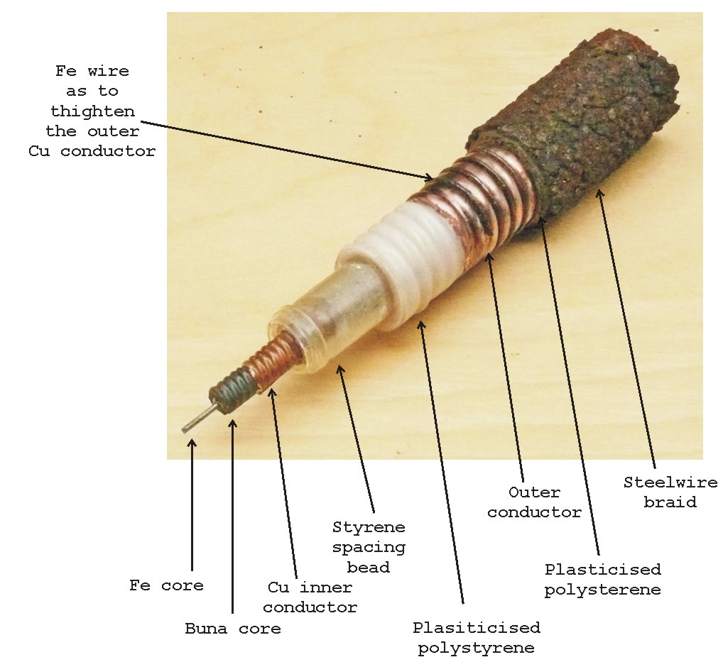
Photo 62 Viewing in detail how this cable was being constructed
(AOB)
Please notice the bead-ring just in front on the left-hand side. My first impression was, that it remained after David Kossen did have cut the various cable sections. Though, the next drawing, derived also from this RAE note 250 shows to us what it really is about.

Drawing 33 Please notice the ring (disk) on the left-hand side. This one is similar to the ring in the previous photo
(NA/GB, AVIA 6 12389, courtesy Phil Judkins)
It is clear that quite some air-spacing being incorporated, reducing the ratio of V / ν. I therefore guess, that ν might be in the order of, say 0.8; whereas most Allied coaxial cables provided a velocity factor of say 0.6 - 0.7. The disadvantage of air spacing within coaxial cables - is that cables become less pressure resisting; also bending should be accomplished with more care. The application within the Mammut system, both disadvantages were not effecting reliable operation.

Photo 63 This photo is providing a good vision how the cable cross section looks like
(AOB)
It seems as if the inner conductor tube is floating inside the cable construction though, it is being kept in place by means of the beads-chain. However, in this case due to mechanical preparation (cable cutting) is has become a bit out off centre.
I guess, that with both our details as well as some of the British note 250, you can quite well determine all the necessary measures yourself.
Quoting from David Kossen's e-mail where he provided the average cable measures.
Binnenste geleider: 7.50mm en
8.00mm maakt 7.75mm gemiddeld.
Afscherming: 23.00mm en 24.60mm maakt 23.8mm gemiddeld
Average measures
Inner conductor (flex tube) 7.75 mm (please note that this is not the Fe wire core!)
Outer Cu
conductor 23.8 mm
There does exist also discrepancy between our cable sample and the one shown on photo 61 derived from the RAE note 250. What they designate copper mash does not exist in our sample. They used a Fe wire as to tighten the Cu outer conductor instead.
On the outside of the cable we find a quite rusty steel braid screening. Often used for 'arming' power cables against mechanical destruction. The British report is non conclusive on whether it does provide some HF screening or not. It certainly was connected onto ground.
The Buna compound was a wide spread German substitute for natural rubber. Luckily to us preserving people, it has the great advantage - that over time it does not deteriorate like natural rubbed is behaving. Over the many decades, > 7 now, it becomes a bit less flexible, that's all. There exist several reports on this subject of which I made a brief selection:
CIOS File No. XXII-20: I.G. Farbenindustrie A.G. Bunawerk Schkopau, Germany
CIOS File No. XXII-22: Synthetic Rubber Plant Buna Werke-Schkopau A.G.
Closing this chapter, we would like to show a properties table.

Photo 64 Our Vacha 726 cable designated in this British note RFC/G/16 did constitute an cable impedance of 62 Ω (> 10 MHz) (according information on report page 20 - its cable impedance is 61 Ω). Maybe of interest is its weight property: 2200 lbs per 1000 yards. I guess, these figures were British estimations, as it is not quite likely they really got a bunch of 1000 yards
(NA/GB, AVIA 6 12389, courtesy Phil Judkins)
Using our very versatile quite old conversion programme we get:
2200 lbs → 997.903 kg say 1000 kg
1000 yard → 914.4 m
We therefore say just not 1000 metres Vacha 726 cable did weight 1000 kg
This table also tells us that the cable outside measure is 25.2 x 1.25 = 31.5 mm. This value is quite well in accordance to the measures David did provide.
A back of an envelope calculation - what was the likely weight of all coaxial cables together used in a general Mammut system (not GAF type F). Let us estimate that each cable length measured, say, 25 metres, we get: 24 x 2 x 25 = 1200 metres in total.
What I never expected, is, that comparing photo 61 with the photos 62 and 63 - the impression of what this cable is about can differ so much. Is this due to the black-and-white versus colour photos or is it due to the way of photo perspective, I don't know? But, without our colour photos we might well have bore a bit different kind of cable in mind.
Marc Simons touched a quite interesting aspect:
Quoting from his e-mail on 11 August
Verder zit ik nog met het ribbelen van de koper-folie. Behalve stevigheid geeft dit flexibiliteit. Maar is dit het enige? Dacht het niet. Dit ribbelen geeft ook een bepaalde elektrische eigenschap. Wellicht leuk om dit eens uit te zoeken. (Mijn vermoeden is dat dit dient voor het creeren van 'dispersie' zodat je niet perfect gematched bent voor maar 1 preciese impedantie, maar dat de kabel zich 'gedraagd' zeg een paar ohm rond de gewenste impedantie. Een kleine mismatch geeft je dan niet meteen enorme problemen. Geen nare peaking problemen etc zoals je bij waveguides ziet)
The aspect of impedance spreading was already bore in my mind, however, my perception was mainly that the application of ribbed Cu might causing a lower critical frequency (cable) application. I believe, nevertheless, that first - optimal energy transfer combined with some mechanical flexibility was the producers main objective. That a side effect of less critical impedance matching might be in accordance to the two different impedance figures of 61 Ω as well as 62 Ω, provided in the R.A.E note 250.
However, I believe also, that it might have been practised to rely upon n x λ cable lengths. In these cases matching at both cable ends becomes less critical anyway. Another aspect, not to be neglected, is that cable matching becomes less critical the longer a coaxial cable is in respect to the applied wave length (stretching effect). In a foregoing estimation of a total cable length engaged, I coined 24 metres. This is already 10 times the applied wave lengths of 2.4 m.
(9)
On 14 + 19 August 2015
Eine Entdeckungsreise
As so often in this survey, I discovered new details on pictures that I (we) have looked at quite often before.

Photo 31a One of my queries was, how was the compensator arm once being moved (driven)?
(courtesy Alain Chazette, from his above mentioned fantastic book)
It appeared, that I should study this photo in detail again.
Photo 43 Please consider both the cogwheel and its pivot on the left-hand side, as well as the grey junction box on the rusty metal mounting frame on the right. By the way, have you noticed, that the remaining grey paint seems to be similar to the one applied on photo 31a?
(Courtesy David & Vincent Kossen)
It is evident, that in someway or another some more details can be find on the genuine NVK Fk2 compensator photo.

Photo 64 My new perception of - essential provisions not yet incorporated in our system description
(courtesy Alain Chazette, from his above mentioned fantastic book, modified AOB)
With some 'good will' two cables going upwards (or downwards) can be seen connected onto a junction box. Comparing with the previous photo 43, we notice that the only difference is that the boxes being mounted at differ sides of the compensator base. Wherefore might these cables have been once used; a repeater (servo or Drehfeldgeber) provision, or should it indicate the arm-deflection-limits, or another option - controlling brakes? Two lines, one for the transmitter and the other one for the receiver section?
Considering the provision of - arm-deflection limits - it might make sense when a motor-drive being used.
Who knows?
I also recognised, that the coaxial-combiner-lines (input and output) have also been fit with matching stubs (Stichleitung). I cannot recognise on the far left-hand photo side, whether the transmitter combiner line did have two Stichleitungen as well; as symmetry is kept everywhere consequently, we may consider that it did. What also being discovered, is that just left of the cable combiner is mounted another Stichleitung, though, this time not facing towards us or opposite, but facing sideward - onto the right-hand side. It therefore is likely that the equivalent transmitter stub is facing towards left.
They might have implemented 102 complex impedance matching devices (Stichleitung) all together!
Quite a number.
Only since today, I recognised vaguely that we can see some glimpse of the driving chain. Please consider also previous chain-wheel on photo 43.
However, the purpose of using a chain-drive is to move the compensator arm some vector to the left and right ( -50° to + 50° against the 0° compensator centre).
Though, how?
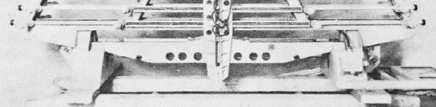
Photo 65 Fore it I have selected some photo details
(courtesy Alain Chazette, from his above mentioned fantastic book, modified AOB)
You might get the impression that the sliding holder base being fixed (tighten) by means of two screws shown left and right.
But, is this valid?

Photo 66 My perception of the 'sliding foot' being shown in blue; the red dotted line is constituting the lower chain section. The black dotted circle representing a cogwheel, being in some way mounted (implemented) into the 'sliding foot' provision
AOB: 29-5'22: The Germans might have designated this provision a "Kufe" which should keep the sliding-arm-pressure at all sliding contacts controlled (within limits); as otherwise the lower-end of the sliding arm would tend to move outwards (lateral).
(courtesy Alain Chazette, from his above mentioned fantastic book, modified AOB)
I believe, that the sliding foot is having a counter piece which moves inside the cast frame (rail) of the compensator. In someway or another - a kind of cogwheel is being pivoted into this provision. Not visible to us, is, whether the driving chain is touching the cogwheel twice or not. Considering the straightness of the lower chain a believe it did not.
Though, how is this provision translating its movement onto a non linear moving compensator arm - against the horizontal slotted line sections?
It popped up in my mind, that the cogwheel might not have been implemented inside the sliding foot arrangement, but in between both compensator-arms. How, we don't know.

Photo 33b In my perception, the compensator arm does have a single long-stretched open guiding slit over almost its casted arm-length. For robustness somewhere in the middle they have implemented a 'turnbuckle'. Please notice also - that what I designate sliding foot being in a different position than the is shown on photo 66
(111 SC 269030 - "US National Archives" courtesy Mike Dean, detail modified by AOB)
This way of linking a horizontal and a vertical movement together is robust, and does not need provisions for controlling a linear displacement onto a sinusoidal changing arm vector.
When you compare both - photo 33b with photo 64 - you might recognise that a sliding feet ridge reaches inside the arm slit. By which means the compensator arm being prevented from bending outwards (towards us)? I cannot say. Maybe, this had been countered by linking both the receiver- and the transmitter-arms together at their far lower ends - just underneath the compensator chassis. How? I have no idea, yet.
Photo 64 I was also intrigued by noticing the cogwheel driving mechanism
(courtesy Alain Chazette, from his above mentioned fantastic book, modified AOB)
Photo 42a It is not difficult to recognise the similarity between both this photo as well as the previous photo 64
(AOB)
Both having a more or less similar cogwheel driving shaft. It becomes evident, that the compensator chassis being delivered with attached driving mechanism and that this provision was not part of the bunker outfit. When you look carefully at both photos (42a and 64) - it is even visible that the metal frame construction on the right-hand side being already attached onto it when the compensator frame being delivered.
Consequently, the entire compensator was delivered integrally as a full operational module. Likely, even the coaxial compensator sections being matched onto the expected line parameters, by means of the quite magic 'Stichleitung'.
On the other hand, this might also imply, that the matching stubs (Stichleitung) had only to compensate for matching- and/or phase-deviations (errors) caused from within the slotted line arrangements.
Isn't it amazing, that careful looking at a photo can solve so many uncertainties? Of course, also bringing up some new questions; though, we might have solved today more questions than new ones came up.
(9a)
On 20 August 2015
preparing a laymen version of our Mammut Survey, I copied the following photo:
Photo 32 Please take a close look at the antenna frame in between the two sections - what do you recognise? Just the white coloured ceramic top disk of a series of Sperrtöpfe!
(courtesy Alain Chazette, from his above mentioned fantastic book)
Photo 36 The remains of such a Sperrtopf device, genuinely acting as a balun (converting an asymmetric signal into a symmetric signal vv
(Courtesy David & Vincent Kossen)
These remains were found nearby the the Mammut bunker in Wijk aan Zee.
(9c)
On 30 August 2015
One of the still unresolved questions, is - how did they accomplish proper impedance matching?
For it I would like to visualise the problem we are facing -
Let us, however, first remember what a compensator unit looks like
Drawing 31a Please compare this device and my next drawing below
(courtesy Alain Chazette, from his above mentioned fantastic book)

Drawing 35 I assume - that most of you will recognise the similarities
(AOB)
As to get a proper PDF version, please click at this line
Our current problem, is, what might the implemented 'complex' Stichleitung Zx impedance have been? They used 102 of these devices in direct conjunction to a Mammut Compensator rig.
We are waiting for Marc Simons' measurements. However, he currently is heavily engaged in urgent engineering projects, and business goes first.
On 3 November 2015
Just today I received Marc's series of Smith Charts - showing the behaviour of our Stichleitung, which device is so essential for properly operating the Mammut (and some Wassermann) Compensator apparatus.
I would like to go first through the 5 photos which Marc and Paul did take about 4 October last month.
Restarting on 4 October 2015 again
Marc Simons told me yesterday, when he joined our annual Slamatan, that he finally got time to set up a network analyser for measuring the parameters of our ominous
Stichleitung
For it he had to prepare a sort of adapter first.

Photo 43 He did it with simple means but still such that it would behave properly
(Courtesy Marc Simons and Paul Reuvers, Eindhoven)
On the left-hand side the coaxial end of our Stichleitung

Photo 44 Viewing Marc's 'adapter' made for matching the wartime coaxial Stichleitung onto first an N-connector and then onto an SMA connector
(Courtesy Marc Simons and Paul Reuvers, Eindhoven)

Photo 45 After having calibrated the network setup onto the Network analyser he could see something unexpected
(Courtesy Marc Simons and Paul Reuvers, Eindhoven)
Viewing the Smith circle plot, it is apparent that Marc measured in steps between 100 and 300 MHz

Photo 46 Marc measured briefly first between 100 and 300 MHz
(Courtesy Marc Simons and Paul Reuvers, Eindhoven)
Currently cursor of the Smith Diagram at 200 MHz.
Please omit some false light reflexions.
What he found was not expected - nowhere was a resonance visible, and the great discovery, was, that when tuning the Stichleitung 'number setting' that the cursor rotated along the circle and it was possible to set or adjust it between pure ohmic low and high as well as pure inductive or capacitive.
It is thus possible to match virtually onto every circumstance.
Marc promised to concentrate next mainly on 125 MHz which was once the most often operated system frequency.
One thing is, however clear, that wide-band operation was by this means not possible, because every time the Stichleitungen (102 samples) had to be readjusted; which was, according a recently got report, 24 hours work.
What a great finding!
On 29 October Marc did send us the following e-mail with attached Smith chart results: It proved, however, that I could not get these out off his e-mail and had to wait a few days more.
The Stichleitung appears to be an adjustable open stub. It acts like a coax adjustable in length simply by turning its knob. All measurements down below are created with a 8753C network analyzer accompanied with a 85046A test set. With this setup we were able to create these S11 measurements (= 1 port reflection measurements). The numbers in the pictures represent the numbers of the adjustment knob, as represented in Arthur his photo's above. Further, we have done some calibration verification, hence, the short, open and terminated measurement (at 50 ohm). This was done to verify that our thoughts are right and that the errors are not too big. (Everybody with some experience with NWA's know that mistakes are easely made ! ;-) We also measured a couple of coax lines on the analyzer to show that our theory about the open stub is right: One is a 85cm coax with open end and the other a 160cm coax, also with open end.
One may wonder why the distance over the outer circle of the smith card is not constantly the same. This is due to the complex plane in the Smith chart, and also there might be some trouble inside the Stichleitung due to frequency dependent loss. Because of this reason it does not behave extremely linear in impedance over frequency, but for small bandwidth purposes it does it's job perfectly well !
The markers in the measurements show 115MHz, 125MHz, 135MHz and marker4 is on 120MHz. It is good to follow one of the frequencies over all these measurement. See for yourself that it runs from capacitive to inductive. The Stichleitung appears to be a very useful and rock solid slotted line compensation device, as shown earlier on these pages. If you store these pictures and scroll down while viewing them quickly, you will see the effect of turning the knob. (I should learn how to create animations...)
Marc's system set-up being described previously.
Please be aware - that our Stichleitung device is > 70 years old, and some oxidation might have occur internally.
Let us look what the results are. In my perception you should know how Marc did calibrate his Network analyser (NWA) set up. Usually one would like to counter all distorting aspects first. Such as coaxial line(s) between the test-set and DUT.
A series of pre-conditions have to be gone through - before the internal processor can eliminate the 'unwanted' parameters.
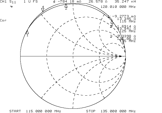
Open coax 160 cm (thus DUT being disconnected)
Open coaxial line of 85 cm (DUT being disconnected)

Stichleitung socket being open (DUT not connected)

Stichleitung socket being shorten

Stichleitung socket finally terminated by a 50 Ω
With these parameters the system is able to 'nullify' all the set up parameters and measurement can be accomplished just as if the Stichleitung being plugged into the HP MWA apparatus directly.
Marc told me last Saturday, that he starts with a series of GIF file measured for the Stichleiter dial set at number 1 - the following numbers gone through in succession; he later decided to go through two dial settings in succession.
This is how the scale dial looks
Please notice: That 125 MHz was the common operational (Mammut) frequency used in the above described Mammut system; represented by cursor Δ 2

Stichleitung set at dial number 1
All essential system parameters being provided

Stichleitung set at dial number 2

Stichleitung set at dial number 3

Stichleitung set at dial number 4

Stichleitung set at dial number 5

Stichleitung set at dial number 6

Stichleitung set at dial number 7

Stichleitung set at dial number 8

Stichleitung set at dial number 9

Stichleitung set at dial number 10

Stichleitung dial set at number 12

Stichleitung dial set at number 14

Stichleitung dial set at number 16

Stichleitung dial set at number 18
Stichleitung dial set at number 20

Stichleitung set at number 22

Stichleitung set at number 24
First I would like to thank Marc Simons very much, for his great commitment!
Not many are able and - willing - to assist our endeavours in such a practical sense.
Thank you very much
Finally
Viewing the implementation of the Stichleitung into the NVK Compensator set up
(AOB)
I would like to add a small comment:-
We have noticed that most of the Δ 2 settings resulted in the upper section of the Smith Chart; hence, behaving mainly inductive (of course, also complex).
This would imply that the NVK type Compensator line did behave at the Stichleitung sockets mainly capacitive (of course, also with an ohmic component).
We might assume - that we have likely reached the conclusion of my Survey.
Was all the many efforts worth it?
Yes,
More than that!
(11)
Apparently - not yet completed entirely!
On 26/29 January 2016
I received the desperately wanted X-Ray of our quite unique - but mysterious -
Stichleitung (tuneable open-end-stub)
Kindly managed by Paul and Marc. You just need to have the right friends!

A wonderful X-Ray (Röntgen) photo of our quite mysterious Stichleitung
Please click at this link as to open it in PDF
I must, however, admit that in some respect I still have some doubts left as to how it actually is functioning.
The (very) transparent grey sections are consisting of aluminium. Albeit, that on the far right-hand side, we are meeting brass (earthing) fingers (lips). Following the connector pin towards the Stichleitung housing, we first encounter a dark-grey ceramic (centring) disk.
On the left-hand side - we notice the tuning provision (scale numbers 1 to 24). Photo taken with the covering Al cap being fit. On the far right-hand side we notice the coaxial contact-pin (Stecker).
More towards the centre we notice a disk like provision. A tubular cylinder is having on its outside a thread-grove (like a lathe-spindle) which, when being rotated, will force the disk to displace up or down (to the left or right).
Likely, this disk possesses a counter-thread (pitch) inside. It is fit with conductive fingers; which are touching the inside surface of the tubular Al Stichleitung tube.
Thus - when the left-hand side mechanism being rotated the disk will move along the drum accordingly.
What is bothering me - how is the moving disk kept in solid contact with the, just visible, centre conductor? On the left-hand side being connected onto the coaxial plug and on the far left-hand side being fixed by the driving mechanism.
We might see a virtual thread, but X-rays tend to look through materials and we likely see the thread of the cylinder (drum).
This morning I did phone Marc and he confirmed what I already expected - that when the left-hand side dial-setting being changed (rotated) the connector-pin at the other end rotates an equal amount. I consider that the cylinder or helix must be of an insulating material; I assume ceramic.
But, this only works when the hollow centre being coated with a conductor inside, likely silver. An Fe body it cannot be according the X-ray photo (the X-rayed section is too transparent). However, another option may be that the helix-thread being outside silvered.
The helix is being used (operated) only occasionally, when new compensator alignment is due. On the other hand, according a Post Mortem report - quite frequent alignments needed to be accomplished; which entire procedure took about 24 hours! We should also not neglect, that we previously counted a total number of 102 Stichleitungen; within a complete compensator frame (comprising a separate compensator module for receiving plus one for transmitting; 2 x 61 samples).
Nevertheless, from a practical point of view I tend to assume that it is silvered on its tubular inner-side.
However, on the other hand - not clear to me yet, how is the inside cylinder with outside tread being attached to earth potential? Is it really?
One gets also the impression that the coaxial connector pin is electrically and/or mechanically interconnected (in some way or another) with the rotating cylinder. (Afterwards confirmed by Marc)
On the other hand, I once concluded that there does not exist a galvanic interconnection between the coaxial in- and outside. Which is in accordance to the Smith charts recently made; these show clearly an open-coaxial-line behaviour.
Who does have the revealing answer?
I hesitate to believe - that this is the ultimate end of our Survey and Entdeckungsreise.
Do you?
Next valid:
Some photos provided by David & Vincent Kossen on the remaining
coaxial cables within their V143 Mammut bunker
Accomplished
Dick van den Berg's antenna beam forming hypothesis,
in respect to the trapezium shape of the applied successive slotted-line
lengths
Accomplished
David & Vincent Kossen's coaxial cable photos which he took
recently in the Wijk aan Zee V 143 Mammut bunker
Accomplished
Compensator (Wellenschieber)
matching by means of 'Stichleitung'
(in progress)
Dead zones
Accomplished
To be continued in due course
(13)
On: 16 August 2020
My wife who is an expert in manipulating photographs and converting them creating a piece of graphic art, showed me her newest creation:
let us first repeat what we so far knew on the way the tuneable "Stichtleitung" was to be connected (linked) onto the (bearing) "Kompensator" device
Photo 26 Stichleitung (GP/N) side view, similar to those shown at photo 23
(our collection)
Photo 25 Viewing a very comprehensive example of the application of matching stubs
(111 SC 269029 - "US National Archives" courtesy Mike Dean)
It appeared that we possess such a "Stichleiting" in our collection
AOB: Please notice the two shafts on the left-hand side, noticing it from the "Kompensator" side!
This pointing onto its application within the a GAF Mammut-F configuration.
However: we at least get an idea how the foregoing showed Stichleitung (Stub) is attached onto the "Kompensator" unit.
Please notice also that the Stichleitung being fixed by mean of a nut.
Drawing 31a Please compare this device and my next drawing below
(courtesy Alain Chazette, from his above mentioned fantastic book)

Comparing now this photo
How could the Stichleitung (Stub) have been kept fixed without an adjusting nut-threat?

My wife traced among the many photographs I took during visiting myself the Kwartellaan Bunker in The Hague
How lucky!
Because to what we know this is the only knowingly remaining GAF as well Kriegsmarine "Kompensator" devices.
Comparing again the Stichleitung (Stub) with the space in which it should be inserted in, we know now that the outside diameter of the Al housing and the foregoing inner diameter of the threat must match!
What is always tricky, are the various sizes (scale) of photographs
The only open query to myself, is: why haven't I noticed it before?
For your better understanding of the matter:
The circuitry of one of the twelve "Kompensator" sections (equally for receiving as well as transmitting)
I hope that this brief addition is enhancing your understanding of the Mammut Kompensator including its correcting matching arrangements (Stichleitungen) (according Stubs)
In my perception time has come to start up an additional webpage, where the Mammut system is explained in a bit more simple way.
I therefore, have created
However, this will not imply, that this current webpage will no longer be extended. I expect, that still new technical matters will turn up, be it from outside sources or popping up in my mind. Consequently, two web pages have to be considered
Since 20 September 2015 a new survey has been initiated, this time focussing on the Wassermann Radar system
(end)
I would like to reflect onto Prof. Hugh Griffith's e-mail from 19 June
If you write a
piece on Mammuts, you should call it 'Compulsive Hoarding'.
He is quite right
- digging into such a subject is often becoming an obsession. Because, you
virtually touch aspects of the past which is, for the time being, becoming a
part of yourself. On the other hand, luckily, not being bothered with the danger
of war, under which all took place. Nevertheless, rather intriguing, is,
that one have to judge layers where general knowledge is reaching a kind of
vacuum. Even late Fritz Trenkle, whom we all owe much, is sometimes mixing up
details, which comes to light when you go into it comprehensively. Being for a
while just at the edge of something is very enervating and I cannot explain why,
is doing something with your brains; this feeling is sensitising thoughts. Like
previous were: Nachtfee, Würzburg repair project, the various joined projects
together Phil Judkins, not at least this website.
If there is someone having additional information or knowledge, please come forward and contact us.
![]()
Please type in what you read.
By Arthur O. Bauer
![]()