
Magnetophon T8 starts running OK
Since yesterday Wednesday 20 May 2015
Status: 1 July 2015
Our T 8 machine starts running more or less perfect.
Please view the brown like capstan-roller-wheel. That proves to be a crucial backbone of the system.
However, we now encounter a drawback, because the AW 1 capstan motor is causing problems due to a kind of internal sparking. Causing, although the motor runs better than ever before, that suddenly a kind of internal motor sparking is causing speed irregularities; being made visible by means of a series of YouTube films.
During a discussion with Dick Zijlmans, he suggested that we should try also the brown coloured rubber-wheel-roller again. Because, the capstan motor originally used within the AEG Magnetophon type AW 1, is running now without problems.

Changing the wheel is simple and after a minute I switched on the T 8 machine. It ran far better than it did during all the previous experiments (this rubber wheel we so kindly got from Bernd Fischer, some months ago)
Dick Zijlmans particularly dedicated his attention upon the most left-hand side tape-guiding spindle, which should be aligned far better.
Using a CD as our current signal source; I was most astonished. Although, there still were, in the beginning, some signs of wow. For it I chose the violin concerto of Johannes Brahms. A violin is a very delicate instrument and wow virtually being increased.

Like during previous experiments, I encountered - that after a while the tape-speed does start running with irregular speed
A quick look at the eccentric arm shows that it has not been entirely rotated anti-clockwise; therefore not pressing enough the rubber roller-wheel-arm against the capstan (thus the tape).
Then I did take a look what might cause this nuisance underneath the tape deck.

Viewing it in more details, I discovered that it is likely that the spring can be 'wound-up' a little bit more (loading the eccentric arm a bit more)
Apparently, on the
left-hand side of the spring there existed just some free space (play)
slack*, so that the
eccentric arm cannot rotate anti-clockwise maximally. This arm is attached
onto the left-hand side of the spring. There existed some slack 'free space' (play)
* between the
centre screw and the left-hand 'spring-eye'.
* Dick Lucas did send me the following comment: Maar 1 kritiekpuntje: speling in het engels heet: slack en geen free space of play. Hi

This brought the final touch and our machine does function the best way possible
Rotating the nut such that the spring will move a bit to the right-hand side. Virtually shortening the shaft that moves to the right-hand side caused by an electromagnet (activated in the: recording- or play-mode).

Then I considered how we can adapt onto the lubrication system of the capstan motor
The rubber lubrication tubes are well visible
The capstan motor should be rotated 90 degrees, so that both rubber lubrication tubes will move underneath the tape deck.

The shadow of the old, by paint covered hole, is quite good recognisable
Dick Zijlmans did point the probable place where once such facility was accessible. Albeit, that this might have been skipped shortly before our T 8 machine started its broadcasting life about 1949/50
Still quite some work is to be done, but it is, Deo volente, likely that we can see some daylight at the end of the tunnel.
It took us, nevertheless, more than two years of intensive commitment.
About the YouTube films: Recording being made and replayed after 183 ms. Equal to the mechanical tape movement of 7 cm (tape speed 38.1 cm/s); being the difference between the recording- and play-head centres. The tone generator is being fed onto the recording amplifier as well as onto the X-channel of the oscilloscope. The play-head output of the T 8 being fed onto the Y-channel of the oscilloscope. Both together (X-Y channels) drawing a first order Lissajous (briefly, differences in amplitude causing a more or less elliptic figure, the argument of the elliptic axis is determined by the actual phase difference between the X and Y signals) . Whereby deviations in amplitude (flutter) and speed (wow) is instantly being monitored. In a later phase, we should repeat measurements and now qualifying it with using a real, calibrated, wow and flutter meter.
Film 185: We view now for the first time a quite good T8 response in regard to wow or speed constancy. Please notice, that in this stage we have not yet solved the incorrect rubber-wheel pressure. Our Lissajous measurement setup is showing the state of affairs in a most objective way. Some of the flutter might be due to - not yet correctly alignment of the tape guiding spindles attached onto the head-arrangement.
Film: 186: The brown rubber wheel is good visible. Interesting, the part of the roller touching the tape is like ring with a slight bigger diameter, maybe a few tenth of a mm. Also the eccentric mechanism is visible.
Film 187: Viewing the Lissajous figure where we record - and at the same time monitor what the play-head similarity is reproducing. Also can be noticed that when the roller pressure being artificially increased that this will cause a deterioration of the wow factor.
(1a)
On 25/26 May 2015,
We encountered a drawback.
Apparently, the capstan motor, formerly belonging to an AW 1 Magnetophon, is showing from the beginning signs of internal (electrical) sparking. In the early stage only been made audible by sparking noise in recording and/or tape replay. In the beginning this phenomenon was found being linked onto the supplied motor voltage; which it apparently no longer is.
Secondly, its effect upon irregular motor speed could not be visualised because it went down under all other speed-deviations-causing-parameters.
Yesterday, I did readjust the first guiding spindle the best way possible. We also lubricated both winding motor bearings. All together we got a better T8 system response. Though, now the nuisance of motor speed irregularities came clearly to light; and can be directly correlated to the sparking motor effects.
My first opinion, we should try getting another motor. When this matures, we should let rewind our current AW 1 motor. However, AW 1 Magnetophon machines is not a common apparatus and only freaks might help us.
YouTube films taken on Monday 25th
Film 188: After various lubrications, and having lowered the guiding spindle a tiny bit, our machine starts running the best way we ever encountered before.
Film 189: Restarted the tape measurement, because it was not yet certain whether the changing pre-conditions would influence the previously shown results. Which it apparently did not.
Film 190: Listening now without viewing the oscilloscope screen simultaneously gives a different experience, as sound irregularities are virtually, for most of us, more difficult to recognise.
Film 191: We are now encountering problems originating from an electrical fault within our AW 1 capstan motor. Maybe not well acoustically noticeable, but there is a straight away correlation between speed irregularities and the arcing sound reproduced in the recording- and the replay amplifier-system.
This latter constitutes a drawback, because we have to find another AW 1 capstan motor. How many are there still around? In the early days of tape recorders, these were expensive and rare devices.
However, I first started with checking whether the winding motors, running at a reduced supply voltage, as these only should keep some stress on the moving tape, are sufficient. First I thought it was not, but later it proved to be all adequate.
Please follow the explications below

My first step was checking whether the various motor operational voltages need correction
But see first the schematic of the T 8 Magnetophon apparatus.

All three motors having a common power line connection. Here represented by the (common) motor-connections 'U'
Though were can I find this common point in our T 8 machine?
Please notice for it the two electrical connections fed onto the neon-indicator lamp. One of it being interconnected with the common line (constituting the most low line in this schematic).

This reference point being earmarked by means of a green binder
Then I started with lowering the overall position of the most left-hand side tape guiding spindle. After some trials and adding some additional thin rings, I believe for the time being a reasonable match being found.
Please consider the previous YouTube films 188 - 191.
First the machine did not perform optimally. But after some time the system began to stabilise and its performance did improve. Finally even better than ever before.
But some nuisance was starting to decrease the T 8 stability performance. It was already found that after the adaption of the AW 1 capstan motor, that a kind of electrical internal sparking (arcing?) was causing and electrical noise during recording and/or replay.
For the first time this phenomenon could be clearly correlated onto speed irregularities of the AW 1 capstan motor.
The only option is getting another one.
Last Wednesday I discussed with Dick Zijlmans how we should implement a sound control panel.
Let us first consider the one I once have designed. We consider this concept being obsolete.

We both decided that that my first concept is providing to limited space for all future options we have in mind
Dick suggested that we should adapt a frame like the one we currently use as our T 8 mounting, consisting of a stainless steel tubular frame.

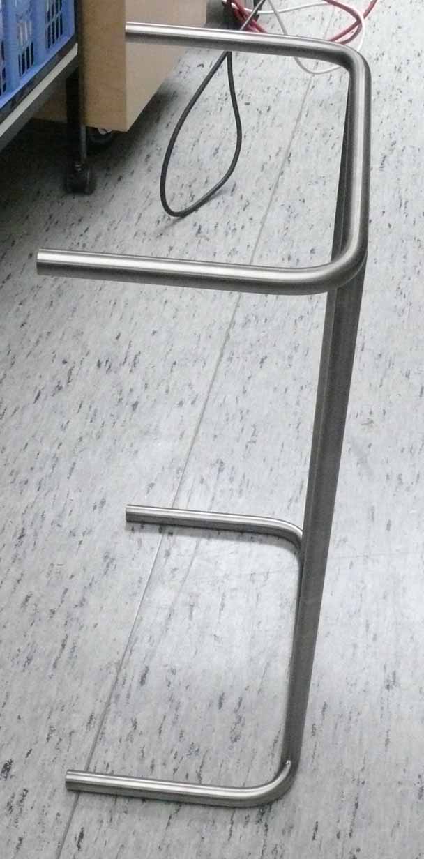
The frame in its essential form

This frame proved to be 'the solution' it constitutes robustness. The machine can be laid on various sides without any danger
Please bear in mind this frame side and the attached control panel should be made that the side measures are identical. So that rather simple both frames can be fit together. Both on the left-hand side as well as, at will, on the right-hand side.
I have redesigned the control, taking into account our recent considerations.
Please notice, that for practical reason the scale of the drawing isn't correct. Though, the measures being provided.

This drawing equals the one shown above albeit, that its size being adapted onto the new vision as to how our control panel should look like
What have been changed, is the fact that no longer the top-plate being kept in a frame, but the top-plate is carrying itself. Leaving also room for extensions and innovations.
(5e)
Jaap Keijzer is back home; what a great luck!
He came along and we discussed all the many problems encountered.
Jaap came to the conclusion that one of the running tape problems when passing the head arrangement being caused by the poor guiding spindles. He decided that it is worth replacing these by new accurately made brass ones.

The brass spindles being made wider than necessary (7 mm)
The former ones made of iron might have been too narrow for the tape used (AGFA PER 525).
Jaap chose for 7 mm width. It proved to be a good choice as the tape ran without vibrations. The only minor vibrations encountered, are those behind the capstan roller towards the last winding-up guiding wheel. Why this is - we don't know yet.
Our regular wow and flutter measurement showed an enormous improvement. However, we still face increasing wow (vibrations) maybe due to the warming up of the AW 1 capstan motor. This phenomenon we have encountered for some time. When we start up with a cold capstan motor this effect is minimal and increases slowly but steady over time.
Jaap asked me whether I would like him restoring the old troublesome capstan motor?
I must admit, I don't not yet know.
He left today and said: I will improved the old motor and we shall replace the current one. This implies, that he first has to replace the lower steel bearing by a new sintered-bronze-bearing.
Let us wait for what he can accomplish.
(6f)
On 1 July 2015
Jaap Keijzer returned with an overhauled roller spindle arrangement. Recently we found out that the current roller wasn't functioning well. It became apparent, that when this roller being hold, thus the tape-back rubbing at its surface, most of the irregularities of speed deviations vanished. At least reduced tremendously. After demounting the poor roller, he discovered that the way it was pivoted on a very poor manner.
However:
We got from Bernd Fischer a spare T 8 deck accompanied with some parts. Among it a rather rusty turn-roller; I have to apologise myself: that I might not use the correct technical expression. My background is in electronics, and not in sound techniques.

You might see some trace of rust left, but Jaap had to compromise between removing all and having to change the shape of this device entirely
Jaap encountered many difficulties. Every part was oxidised heavily and were so rusty that after putting it for a while in a special anti-rust solution, that it still was necessary cooling parts down to - 50° C and heating up other sections at once, with some additional luck, he could finally dismantle it entirely.

Some parts had to be made additionally, because these were lacking

The overhauled roller shown entirely in pieces
YouTube film
Film 193: Viewing the overhauled roller mechanism. The behaviour of the tape system improved quite much. Albeit, that we have to change the AW 1 capstan motor in due course. You might seeing some speed irregularities, but these being caused by Jaap's fingers loading the winding-up-carrier-disk.
Our next action should be focussing on to the AW1 type capstan motor. Which does need special attention.
We have currently a second one available.
Because its bearings need special attention.
I therefore suggested to Jaap Keijzer, that we should take the field-winding middle section of the second motor and changing it for our current one. Because I estimate, that the current speed irregularities (fluctuations) being caused by some insulation failures in the current motor. The end-sections and rotor looks fine, and might still be used.
To be continued in due course.
By Arthur O. Bauer
![]()