Magnetophon Project
Bringing the just obtained
AEG type K8
studio recorder system
in a working order again
Project initiated on: 11 March 2013
Status: 20 February 2014
Please notice the entire text first again, because a bunch of new information has been provided by Mr Friedrich Engel. New additional information is provided by Manfred Firnhaber (5 correction)
1 - 2bc + 3 + 4a + 4b + 5 correction + 6 + 7 + 7a + 8a + 9a + 10
This apparatus is donated to our Foundation by a most generous OLD man (HAM) from Belgium
The leading father of this intriguing new project will be our assisting volunteer Dick Zijlmans! Sound recording and its reproduction is his great penchant!
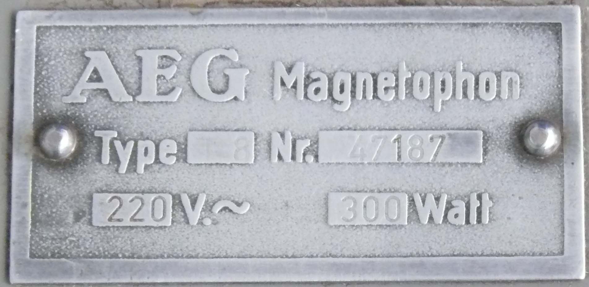
AEG Type 8 (= K8), Serial number 47187
We might consider that 47 pointed at the production year 1947, and 187 is a kind of running serial number
Just two years after the conclusion of the war in Europe, even before the Bundes Republik was established.
It is most likely that this was arranged with special permission of the Allied Occupation Forces, most likely the Americans, maybe the British Authorities as well.
Its first user was one of Germany's leading broadcasting organisation. I was told, that this particular apparatus was being operational during the early experimental FM (UKW) broadcast transmissions, from 1949 onwards up into the 1950s.

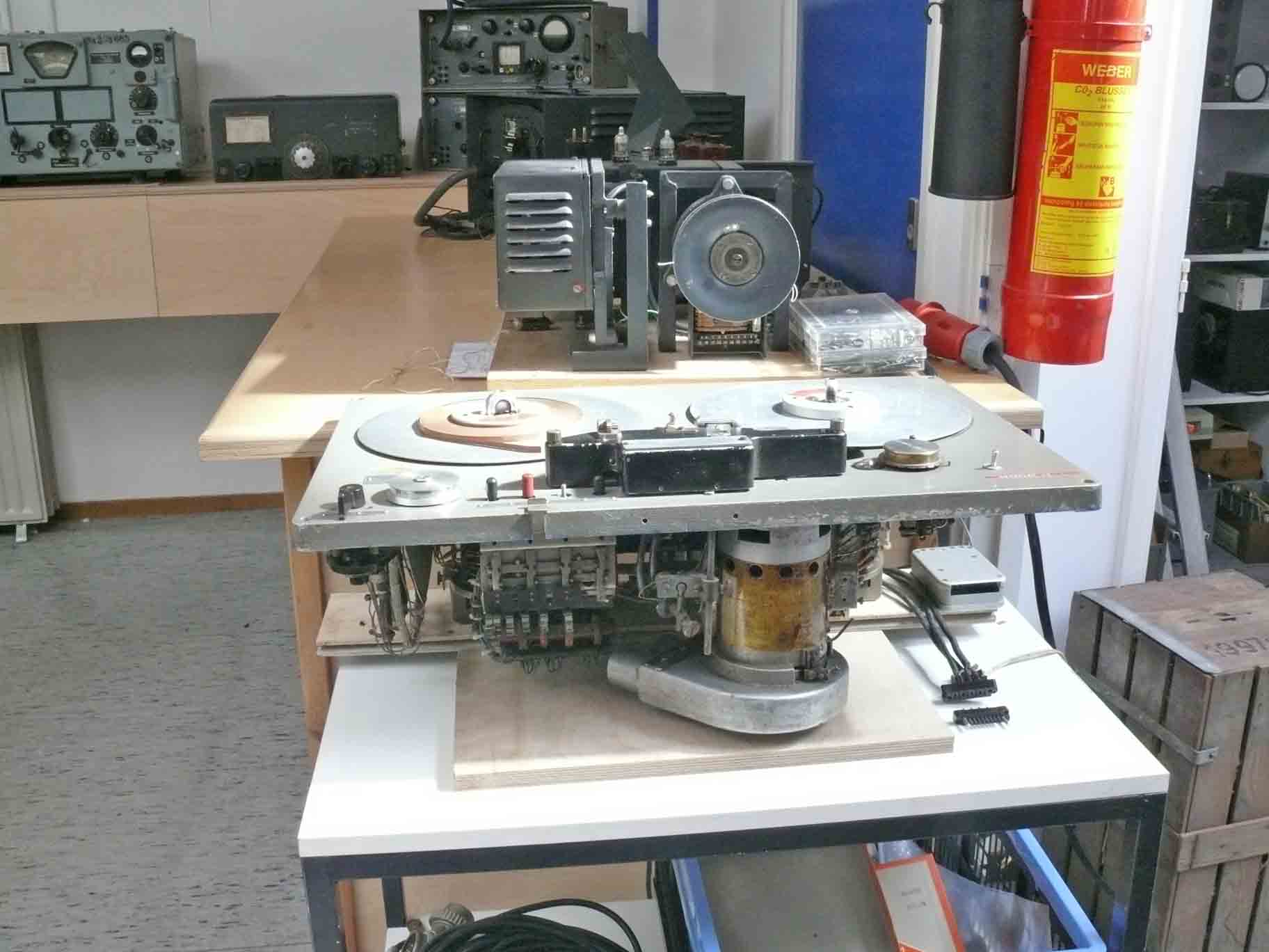
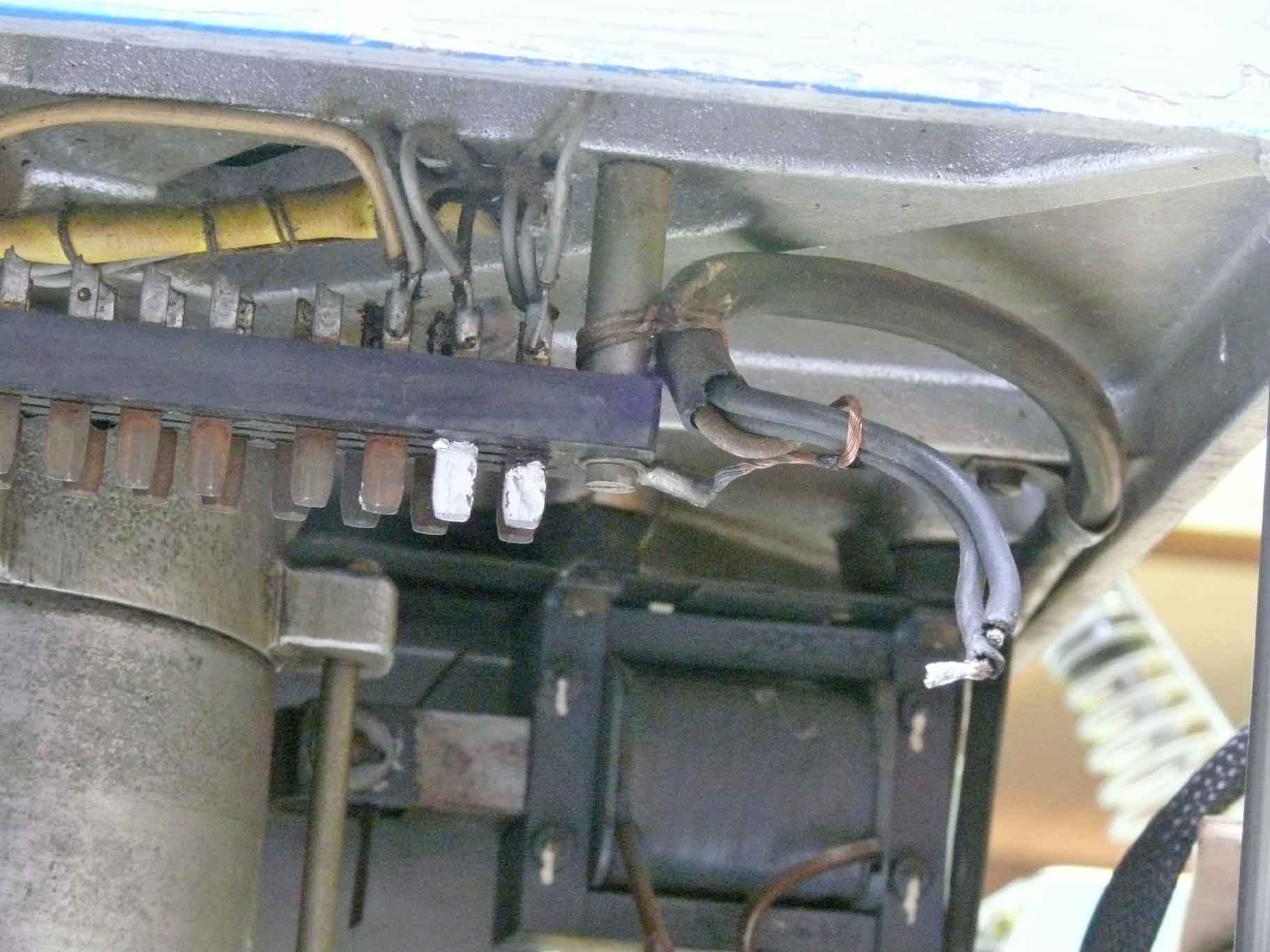
Before turning the chassis downside up I took the opportunity to take some pictures of what is underneath it
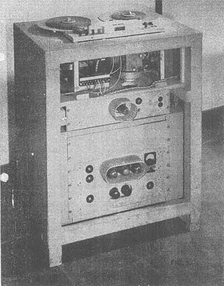
The wartime AEG Magnetophon type K7
Please notice for more details the British BIOS 951 report
Mr Friedrich Engel corrected my Magnetophon type estimation:
Das Bild mit der Legende "The wartime AEG Magnetophon type K7" zeigt keine K 7, sondern das für die RRG gebaute Modell R 22a, Ausführung mit Hochfrequenzvormagnetisierung; das Kürzel "HTS" bedeutet nach aller Wahrscheinlichkeit "handgesteuerte Truhe, stationär". Das Laufwerk entsprach weitgehend dem des Magnetophons K 4.
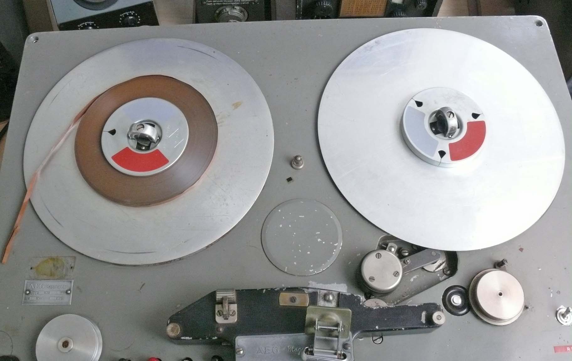
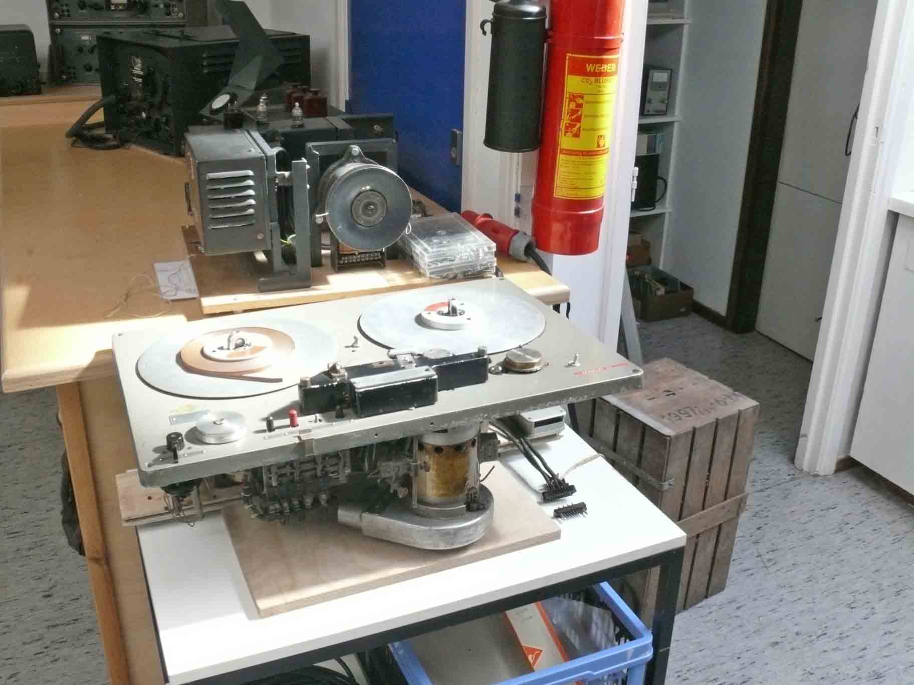
The tape deck of our AEG type K8 Magnetophon
Please notice the replaceable 'head assembly' Viewing the centre cover-lid, this machine never was provided an integrated timing clock
The donor used a German electrical clock, which might have switched the recording system; though, most likely was used in their broadcast studios.
Sadly, just not visible are the control push buttons like the ones in the previous photo. The apparent difference is that the recorder deck is broader than was the wartime K7 machine.

Please compare both this photo with the first one on this web-page. It is clear that some similarity exists. Particularly in respect to the two cooling outlets of the main 'capstan' motor
Viewing it from a different perspective, we will later see, that there is far more in common. Of course, also difference are existing; as progress have been made in the meantime.
Mr Engel pointed that according his understanding there is something curious with our machine type K8 it could be an T8, but it isn't either!
Quoting:
Sehr geehrter Herr Bauer,
das Typenschild der Maschine 47187 scheint mir eher die Bezeichnung "T 8" statt "K 8" zu tragen. Das deutet darauf hin, dass diese Maschine bei AEG Hamburg gebaut wurde, nicht in Berlin. Vor allem die recht breite Frontplatte spricht für "T 8" - beim K 8 standen die 30 cm-Bandteller rechts und links über die Frontplatte hinaus.
Allerdings entspricht Maschine 47187 weder dem einzigen bekannten AEG-Prospekt für T 8 (siehe AEG_Magnetophon_T8_Prospekt_B.pdf) noch dem als Abb. 233 im Buch "ZEITSCHICHTEN" gezeigten Modell T 8f. Die Form der Umlenkrollen ähnelt eher derjenigen des Magnetophon K 7 ( "ZEITSCHICHTEN" Abb. 235). Auch die Ansicht von unten der Maschine 47187 zeigt Ähnlichkeiten mit der K 7-Variante in Abb. 237.
Meine Vermutung: es handelt sich um ein Hamburger Entwicklungsmodell, also um eine Zwischenstufe zwischen K 7 und T 8. In den ersten Nachkriegs-Jahren scheint die Entwicklung der AEG-Magnetophongeräte in kleinen Einzelschritten erfolgt zu sein; sobald zu viele Varianten vorhanden waren, bekam der aktuelle Stand eben eine neue Bezeichnung.
Dass es sich bei Maschine 47187 um ein Einzelexemplar handelt, dürfte erklären, warum sie nicht im regulären Studiobetrieb eingesetzt wurde, sondern - der Erläuterung "being operational during the early experimental FM (UKW) broadcast transmissions, from 1949 onwards up into the 1950s" zufolge - im Bereich der UKW-Entwicklung.
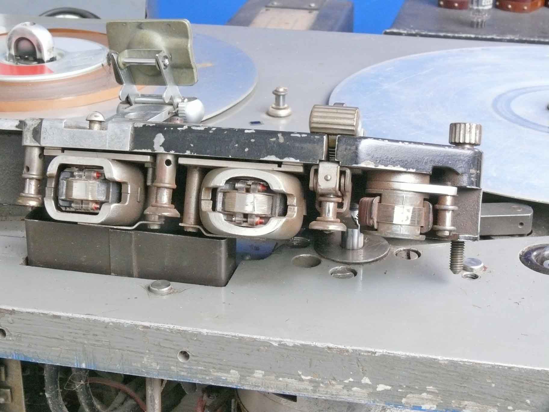
Before we start with peripheral electronics, please take a quick look at the head assembly
When you take a closer look, you might notice that the head-cores are made from regular transformer like sheet material. Ferrite was not yet adapted for these kind of techniques. Might even not have been available, as Philips the inventor of this material was not thinking of the applications in this particular field.
My friend told me that its tape speed is 38 cm/s, whether this was AEG standard in 1947 I do not know. Originally they used, according the BIOS 951 report: 77 cm/s.
What is a recorder deck without accompanied electronics?
A leading organisation in Germany was (is?) IRT, which stands for 'Institut für Rundfunk Technik' This organisation did a lot for the German Broadcasting Organisations after the war.
Friedrich Engel provided as a result of an e-mail exchange the following information:
Die Grafik "Historie des IRT" stammt von der website
http://www.irt.de/de/irt/historie-des-irt.html - hier wären also Urheberrechte zu beachten.

Front panel of Verstärker module V47/2
My guess: '47' may have a link to the year 1947
I received a very kind reply by Mr Friedrich Engel via an e-mail:
"My guess: '47' may have a link to the year 1947": leider nein, die Übereinstimmung ist ein reiner Zufall. Rundfunk-Standard der Jahre 1946 … 1952 waren die Aufnahme-Verstärker V 47 (bzw. V 47b - Frequenzbereich bis 15 kHz erweitert, statt wie zuvor nur bis 10 kHz) und V 46 (V 46 d) für Wiedergabe. Der V 41 hat andere Aufgaben, die in der Datei N420523A.PDF - "Ein neuer Vor- und Hauptverstärker der Reichs-Rundfunk-Gesellschaft" - beschrieben sind. Nach meiner Erinnerung war der V 41 der "Vater" der neuen Gerätegeneration "V 41-Technik", zu der auch der Trennverstärker V 42, ein Kleinleistungsverstärker V 43 und ein Leistungsverstärker V 44 gehörten. Siehe auch
http://www.irt.de/IRT/publikationen/braunbuch.htm.
(1)
However,
these kinds of modules were plugged in a slot (Einschubtechnik)
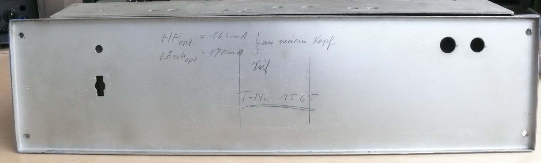
Taking off its front panel we notice: HFopt = 16.5 mA; Löschopt (optimal HF-Erasing head current) = 170 mA. Both to be adjusted for new heads. T-Nr. 1565 is the serial number of this module in the organisation
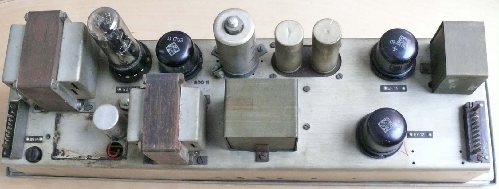
Viewing module V47/2 from the top. The involved valves are: EF14 - EF12 - EDD11 and a rectifier EZ 12 (a quite power full type) The plugs on both sides are of the so-called Tuchel type; very reliable types and widely adapted!
Very interesting, in my perception, is the way the connected being made. Not like in American apparatus at the far end, somewhere deep in the rear of a slot; though just quite near to the front-panel! Providing very simple to access interconnections.
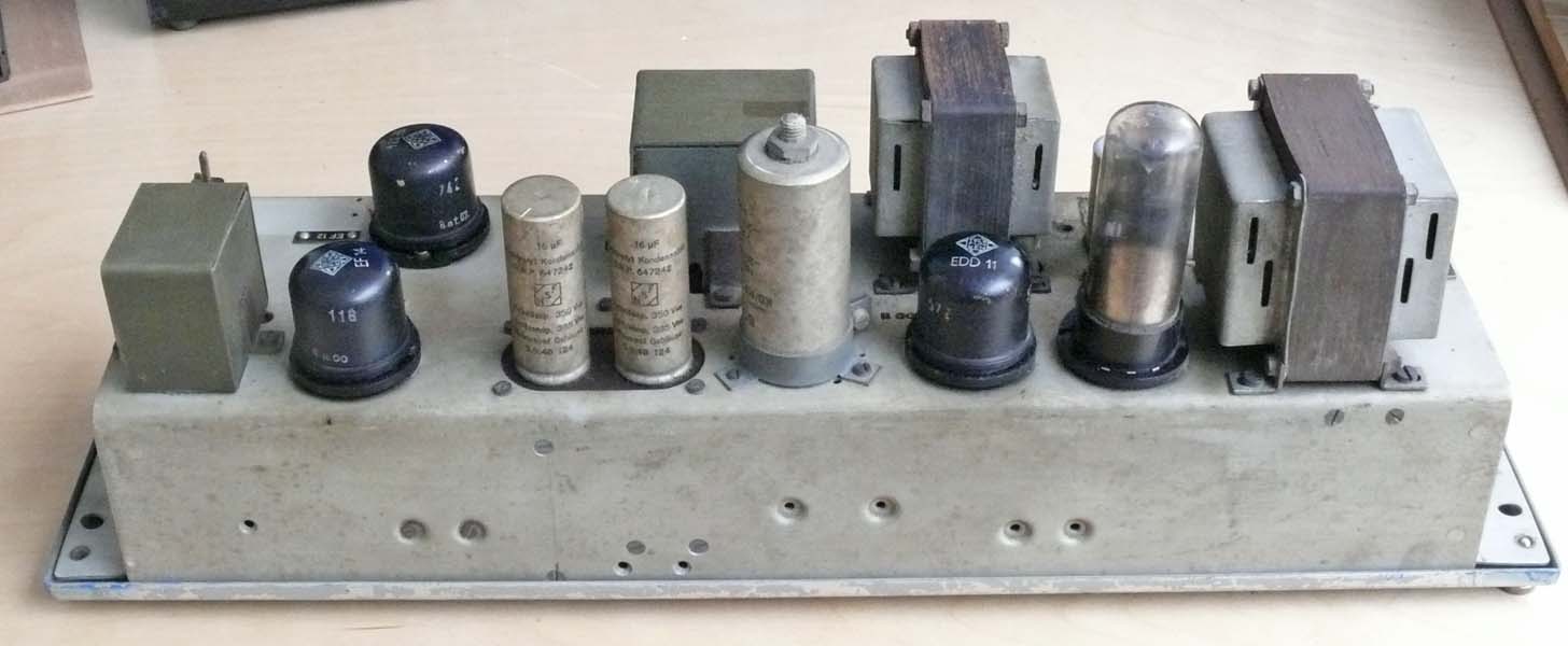
Viewing V47/2 from a different perspective

Viewing what is underneath it, though at the same time the section just behind its front-panel
(11)

The quite famous module V41
The meaning of MV VI is not entirely clear to me; it might have stood for 'Magnetophon Verstärker' number 4.
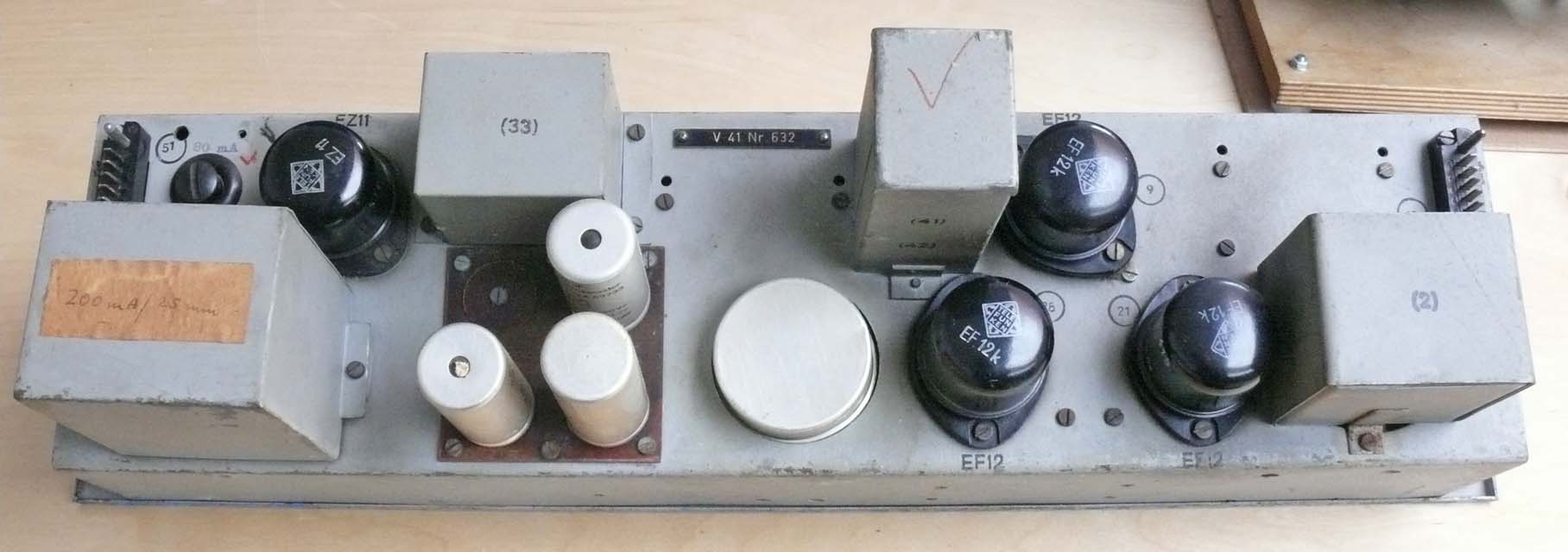
Viewing V41 more or less from above
From left to right: EZ11 (rectifier) - 3 x EF12k, where 'k' is meaning 'Klingelfrei' which stood for 'minimal sensitivity to ringing'; mechanical (light) shocks do not cause the valve grids to vibrate much.
Whether these types where especially produced, or that they were particularly selected after production, I cannot judge.

Looking what is behind its front-panel. In the centre an amplification selector
On 13/14/15/18 March 2013
Together with Dick we approached first the modules V41 and V47b (V47/2)
The schematic of the V41 necessitated some processing especially in respect to cleaning it and restoring the many interconnections.

The Vor-und Hauptverstärker (pre- and main amplifier)
The processed V41 schematic (please compare the upper left-hand side down of the text corner, as to get an idea how it after all has been improved.
Click, please, on the schematic as to open it in an A3 PDF format
However, the schematic of the module module V47b (V47/2) did not call for a further processing. Also marked on the far right-hand side: A/V47b/1
Please click here as to open its schematic in an A3 PDF format
Quite curious to notice RTI; would this mean that IRT should be RTI? Likely than standing for Rundfunk technisches Institut. I cannot give the answer. However, Dick persists in his meaning, that he only knows about IRT
Nevertheless, its purpose is: pre-amplifying the recording signal, as well as providing both the 80 kHz erasing (head) current and the 40 kHz HF-bias current for the recording head.
Our second move was finding out how the Tuchel connectors used for in- and output interact.
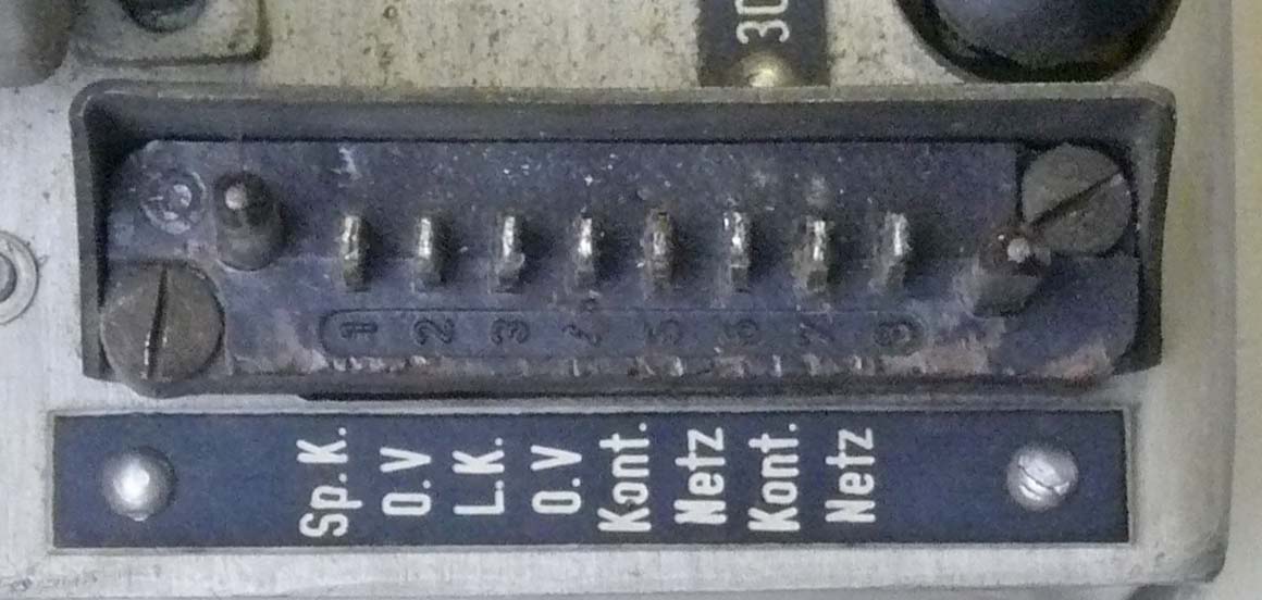
The 8 pins Tuchel output connector
Both Kont. marked connections can be used for monitoring current consumption, or maybe being used as to switch the unit in a standby mode?

Viewing the 8 pins Tuchel female counter-connector
This query has luckily been solved, as a very good friend of mine possesses 20 sets (male + female). I have asked him, why?
He told me, that these were used onboard of some Dutch ships, particularly for pluggable modules. It might even have been up into the 1990s. I still wonder, why it is impossible to find these on the web. What I traced were only two male samples put on EBay by private persons. Even commercial connector deliverers pointed at these two samples. However, nowhere any sign of them in catalogues.
When some of you would like to discuss matters, you can contact us at:
![]()
Please type-in what you read
However, not yet understood when we collected these modules last week in Belgium, is the purpose of the filters W55 and W56.

The lower schematic represents Filter module W56. Maybe 50 kHz should be read 50 Hz?
W 55 is to act as an input filter for both V41 and V47b (V47/2) modules
W 56 is the output filter to V47b, in particular in between the recording output designated Sp.k (Sprechkopf) head and the cabling onto the recorder head assembly; as well as for filtering the mains fed onto the V47b transformer.

The filters were quite neatly built. On the right-hand side the filter covered by a mu-metal-sheet. On the right hand side the cables have to be soldered, on the left a 8 pin-Tuchel connector is provided

The dual capacitor marked 6 and 5 is part of the mains filter. The pot-cores might be made of dust-core material. You can, however, notice that the later pot-core shape originate from German, even pre-wartime, design
In my perception - can we trust the dual suppressor C which is loaded by 220 V AC? Maybe we underneath should replace it by means of two more reliable (modern) types; leaving it as genuine as possible.

A view onto the other plane of the this filter

Accompanied to the Magnetophon outfit is this chronometer. The T-numbering is indicating that it belonged to the inventory of the same Broadcasting entity
On 1/4 April 2013
I continued with taking some photos of Dick Zijlmans' new working space. The previous premature table was occupying space necessary for other kind of demonstrations
Viewing it from a slightly different perspective. The section underneath is better visible
On 7, 10 and 11 June 2013
Due to circumstances not in my hands, progress in the Magnetophon project is being quite hampered.
I am therefore very pleased with the reaction of Manfred Firnhaber, who is already for decades interested in Magnetophon techniques.
I would like to let you share his wide expertise in this field; as it is always difficult to catch those having relevant sources of information yet. We have to bear in mind, that we are dealing with facts and circumstances which occurred more than 60 years ago. In those post war days - who cared what the next generation would be interested in? Technique progressed rapidly, and the regular vision was maximally focused on a life cycle of 10 to 15 years; say, the instance spare parts should be kept on stock (at supply) obligatory.
In many respects it is five minutes past twelve o'clock.
Nowadays our only option is the route of 'reversed engineering'. Following this route is also having its own charm. Our recent Nachtfee survey (eventually consisting of 27 different web-pages) shows how thrilling such a route can be.
Under all circumstances one should show persistency.
However, quoting (in italic) from e-mails which I received today and previously on 7 June.
His first e-mail of the 7th:
Ich lebe seit 65 Jahren in Hamburg und habe als Jugendlicher noch T 8-Laufwerke in Betrieb gesehen. Ich besitze seit 20 Jahren eine funktionierende T 8f von 1951 (auch T 9, M 10 usw von AEG-Telefunken) und technische Unterlagen auch über die verschiedenen T8-Versionen und will Ihnen gerne bei der Identifizierung und Restaurierung Ihres Gerätes helfen.
Vermutlich ist es keine Fälschung (die kann es gegeben haben), deshalb haben Sie dann eines der ersten T8-Serienlaufwerke von 1947(dem ersten Produktionsjahr) aus der Krochmannstraße in Hamburg.
--Meinen herzlichen Glückwunsch!!!--
Der Tonmotor entspricht nicht der Serienversion und auch nicht die linke Umlenkrolle. Der Rangierschalter ist nachträglich versetzt worden.
Aber das läßt sich ermitteln.
Text section in colours have been implemented additionally. It might make sense for you to re-read the entire text - as the additions may change the entire understanding of a quotation.
On 10 June we received the following e-mail:
Einem befreundeten Kenner der Tonstudiotechnikszene bei den deutschen
Rundfunkanstalten und auch mir war sofort klar, daß dieses Gerät nicht
unter dem Einfluß des RTI oder des NWDR noch nach 1951 betrieben worden sein
kann. Dann hätte es schon eine Alu-Rollenanordnung mit Filterhebel, wie sie
später bei der T9 aus matt verchromtem Messing waren vor dem Bandeinlauf in den
Kopfträger.
Die Anordnung des Rangierschalters deutet auf Umbauten durch Herrn Vollmer hin,
der den süddeutschen Raum beherrschte. Damals versuchten die Besatzungsmächte,
das föderale System nicht nur politisch, sondern auch technisch zu fixieren.
Zentralismus, hier AEG mit Zentraltechnik vom NWDR und RTI alle in Hamburg war
schon eine bedenkliche Anhäufung. Das Hamburger "Rundfunktechnische Institut-RTI"
war in einer wunderschönen Villa im Mittelweg in dem sehr schönen Stadtteil
Rotherbaum untergebracht und vom NWDR-Funkhaus Hamburg zu Fuß gut zu erreichen.
Von dort würde ein Hamburger freiwillig nach nirgendwo
anders hin auf der Welt seinen Arbeitsplatz verschoben haben wollen. Als dann
viel später die Studiolaufwerkfertigung von Wedel an den Bodensee verlegt werden
sollte, haben sogar einige ARD-Anstalten protestiert. Nachträglich kann man
sagen, was soll´s. AEG-Telefunken hat es nicht geholfen.
Nach dem Umzug der Hamburger Mitarbeiter nach München verschwand der Name und es
blieb der süddeutsche IRT.- Das RTI war nach dem Krieg die zentrale Redaktion
des Technischen Braunbuches und mit der Zentraltechnik des NWDR prägend bei der
Entwicklung der Magnetbandlaufwerke bis zur T9u.
Falls Ihr Tonmotor mit der Bandgeschwindigkeit 38 lauft, wird er auch von Herrn
Vollmer eingebaut worden sein. Das Original lief mit 77cm/s.und sieht anders aus.
Der von AEG/Telefunken nachgerüstete Tonmotor für 38 sieht auch ganz anders aus.
Es gibt Schleifspuren auf der Gehäuseoberfläche Ihres Gerätes, die
möglicherweise genau dort liegen, wo Eduard Schüllers Mannschaften die drei
Umlenkrollen vor dem Kopfträgerbandeinlauf positioniert hatten. Vielleicht
können Sie dort auch noch die Bohrungen für die Achsen nachweisen. Der
Rangierschalter sitzt eigentlich in der Nähe der Drucktasten. Dort muß im
Gußchassis ein Loch sein. Bitte senden Sie mir ein Bild des Bereiches linke
Umlenkrolle-Rangierschalter, dann kann ich es mit meinen Bildern und meiner T 8
vergleichen.
Ich habe nicht verstanden, welches Bauteil Ihr Freund eingebaut hatte.
Der Gußausschnitt für die Banduhr (damals hieß sie noch Filmuhr) scheint mit
einer Kappe abgedeckt worden zu sein (geklebt?). Die auf einem Foto abgebildete
Banduhr ist so ähnlich bei anderen T8-Laufwerken von Vollmer in die rechte
Umlenkrolle eingebaut worden. So ähnlich, wie bei der M10 später.
Der Kopfträger R18 ist original aus der Zeit. Die Köpfe sind neueren Datums und
wurden so noch in den sechziger Jahren geliefert. Die Mu-Metall-Abschirmung des
Hörkopfes ist noch original. Die Sprechkopfabschirmung ist später eingebaut
worden.
Im Auslieferzustand waren die Kopfbandführungen für 6,5 mm breites Band
ausgelegt. Wenn Sie die auf 1/10 mm genau messen könnten, lassen sich eventuell
auch Rückschlüsse über die verwendeten Bänder machen. Vielleicht ist es sehr
früh in den privaten Bereich gekommen.
Der Verstärker V 47 gehörte damals beim Rundfunk dazu. Der Wiedergabeverstärker
des Rundfunks wäre der V 46 gewesen. Später endeten die Bezeichnungen für die
Wiedergabeverstärker auf 7 und die der Aufnahmeverstärker auf 6. (V 86/87, usw).
Die Filterschaltungen sollten wohl das Eindringen der starken HF verhindern.
Vielleicht war das Gerät zu Meßzwecken eingesetzt und es kam auf dem
Frequenzgang nicht so sehr an und hat den V 41 genommen, weil er
einstrahlungsfester war, oder der V 46 ist einfach nur verloren gegangen.
On 11 June 2013
Manfred provided new and additional information:
Der "Gleitstift" ist ein Überbleibsel der Laufwerke R22a, die ab 1939 von der AEG geliefert wurden und ab 1948 durch Herrn Vollmer. Beim Lesen dieser Braunbuchmitteilung reibt man sich verwundert die Augen, aber es war so zum späteren Leidwesen der AEG-Leute im Norden.
Later he additionally implented: Hier wurden die alten Herren und Geheimräte von damals von einem der Ihren auf den Rücken gelegt. Zu der Zeit lieferte AEG ja bereits die B – R 28 (Verkaufsbezeichnung: AEG Magnetophon T8) und mit dabei war just Ihre Maschine auch.
Selbstverständlich am Anfang nur mit Genehmigung der britischen Besatzungsmacht, die auf AEG und Seifert natürlich ein Auge drauf hatten.- Da wird man sich allerdings nicht kleinlich angestellt haben, wenn die amerikanischen Freunde auch welche abhaben wollten, um am technischen Fortschritt beim Erfinder teilzuhaben. Es wäre interessant zu wissen, ob außer beim NWDR diese ersten Maschinen T8 bei süddeutschen Rundfunkanstalten überhaupt in nennenswertem Umfang eingesetzt wurden. - Der Einsatz Ihrer Maschine war vermutlich von Anfang an ein besonderer.
Beim R22a war er
als Rückspulhilfe für den gesamten Bandwickel vorgesehen, weil diese Maschinen
keine rechte Umlenkrolle hatten und keinen Bandabheber vor den Köpfen im
Kopfträger (z,B. R 7a von 1940). Der Bandabheber kam erst mit dem R18, den Sie
auch haben und der auch für die T8 (Rundfunkbezeichnung B - R 28) vorgesehen
war.. Er ist dem der K8 ähnlich, aber schon weiter in Richtung R19 (für T9, T9
hu, T9u) durchkonstruiert. Die mechanischen Abmessungen des R19 wurden dann für
die M5 (damals nicht zum Braunbuch konform) von Telefunken beibehalten, aber mit
einer anderen Steckverbindung zum Laufwerk. Vielleicht war der große
Siemens-Stecker zu teuer?.
5
Eines der Bleche hatte ich als Schleifspuren gedeutet. (hier muß ich einfügen,
daß das Laufwerk in einem hervorragenden mechanischen Zustand ist). Wenn unter
diesen Abdeckungen Spuren für die Befestigung von Umlenkrollen zu entdecken sind,
können Sie einigermaßen sicher sein, eine der ersten Serien-T8 zu haben (vermutlich
hat man mit Geräte Nr. 100 für die Auslieferung angefangen, damit es nicht zu
armselig aussieht). *Korrektur
zur T8: Inzwischen habe ich das Bild einer T8 gesehen von 1947
mit der Baunummer 26. Man hat also doch unter hundert angefangen. Allerdings
wären das eigentlich sehr viele im ersten Jahr des Produktionsbeginns, denn die
Gesamtstückzahlen sollen auch nur einige hundert gewesen sein. Der NWDR hat
diesen Gerätetyp 1947/48 eingeführt.
Man war ja eine Weltfirma, wenn auch auf dem Hinterhof
zusammen mit einer Wäscherei bei der durch den Krieg nicht zerstörten Fa.
Röntgen-Seifert (jetzt General-Electric), die ihre Röngenröhren bis dato von der
AEG geliefert bekamen. Übrigens befanden sich einige Straßen weiter südlich die
Edelschmieden Maihak und Plath.
Das ermittelte Maß der Bandführungen für die Bandbreite würde mich schon sehr
interessieren. *
On 26 June I received Manfred's correction.
For historians may be interesting, is that both his previous estation as well as
his new understanding is recorded.
Zum ersten Bild:
Dort bei der Metallabdeckung ist der Platz für eine Leitrolle. Eine weitere
Rolle war links neben der Filmuhrlochabdeckung (so bei 20Uhr30). Die Dritte
Rolle war da, wo jetzt der Rangierschalter sitzt, und der Rangierschalter war
neben der Umspultaste. Das war sehr praktisch, weil schnell mit einer Hand zu
bedienen. Vermutlich wird die alte Befestigung durch die nachträglich
angebrachte Rolle abgedeckt.
Mit der komplizierten Rollenanordnung wollte man den Einfluß des Abwickelmotors
auf die Tonhöhenschwankungen abmildern und mit einer gewissen Dämpfung durch ein
zähes Öl in den Gleitlagern für einen zusätzlichen konstanten Bandzuganteil
sorgen, um den Bandzug nicht im selben Maße ansteigen zu lassen, wie der Wickel
abnahm. Die Erfolge waren aber wohl so gering, daß mir keine Maschine bekannt
ist, die von damals bis heute in diesem Zustand überlebt hätte. Sie sind wohl
alle umgebaut worden, weil das Bandeinlegen ziemlich umständlich war. Hier
setzten dann die Zentraltechnik und das RTI an (Hauptsächlich wohl Herr Gondesen)
und bauten eine Filter- und Bremsrolleneinheit mit dem berühmten Filterhebel für
ganz tiefe Frequenzen (und Klebestellen) ein. Das Gerät nannte sich dann T8f .
Diese Konstruktion wurde dann für die T9 übernommen und dort noch etwas
verfeinert.
Die Tastenknöpfe sind nicht von damals. Der für die Halttaste hatte noch einen
Stift, der seitlich nach 13 Uhr zeigte und beim Betätigen der Halttaste den
Bandabheber auslöste.
An der Unterseite der rechten Umlenkrollenachse könnte ein
Gewindeschneckengangsein, Der diente dann über eine lange Welle zum Antrieb der
Filmuhr. Für 76 war das Original hinreichend genau. Für 38 konnte man nur
schätzen. Die bei Ihnen verwendete Uhr ist da sehr viel genauer und komfortabler.
Der eventuelle Bandendabschalter ist nachträglich. Das hatten nicht einmal die
T9-Varianten.
Der Bandendschalter kam erst bei der M10 und dann aber richtig gut
durchkonstruiert. Der in der M15 ist dagegen schon wieder ein Rückschritt.
On 15 June 2013
Nun weitere Details:
Die Truhen waren seinerzeit (nach dem Krieg) aus Holz mit Winkeleisenschienen zum Einschieben der Laufwerke. Das Design war vom Bauhaus-Stil inspiriert und nach meinem Geschmack eigentlich stilistisch viel moderner als die späteren Stahlkonstruktionen.
Unter der Laufwerksplatte waren links und rechts 3 cm Winkeleisen als Rechteckrahmen mit den Maßen der Laufwerksbreite und bei meinem Gerät mit der Höhe 21 cm, damit alle Bauteile frei hingen, wenn das Gerät auf einer Platte stand.
Die Befestigungslöcher für die Winkeleisenrahmen sind auf der Laufwerksplatte Ihres Gerätes gut zu erkennen. Bei Gelegenheit und Interesse könnte ich Maße und Fotos meiner Truhe senden.
Vielen Dank für das Bandführungsmaß. Die 6,25 mm für die Bandführungen sind viel zu eng. Ich habe keine Erfahrungen über diese Maße bei Vollmer-Maschinen. Da das Laufwerk mit 38 laufen soll, ist irgendwann eine Umstellung erfolgt vermutlich mit Teilen, die noch die Reichsrundfunkgesellschaft kennengelent hatten oder von dort inspiriert waren. Wenn alle Bandführungen so eng sind, müßten da eigentlich unbedingt noch Scheiben dazwischen sein von jeweils mindestens 1/10 mm. Selbst die engsten WIDIA- Bandführungen neben den Hörköpfen waren nie enger als 6,27 mm ausgeführt. Bei noch engerer Führung wird die eigentlich offene Bandkante viel zu stark beansprucht, wenn der Bandhersteller an der oberen Toleranzgrenze geschnitten haben sollte. Die eigentlich offene Bandkante hatte während eine normalen Bandlebens schon nichts zu lachen. Aber mit zu engen Bandführungen wird das Band schnell ruiniert.
As to cope with the Magnetophon deck when it is under test, I have made a drawing of a frame, which is to be made from stainless steel

The upper tube ends will be each fit with M6 screw-nuts, as to facilitate direct mounting of the tape deck frame. Spacing between the two U-sections 660 mm
On 28 June 2013 (14 July)
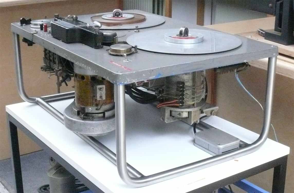
We eventually obtained the new Magnetophon mounting frame
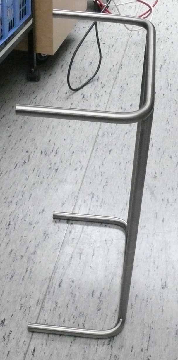
The relevance of this photo, is, that it shows the newly obtained mounting frame without too much perspective distortion

Please compare this photo with the previous one. The outside pointing vertical legs is due to the perspective aberration (please regard the perspective distortion of the table legs)
The perspective aberration is seemingly a bit less

That this frame has been welled soundly is quite good visible
Turning the T8 machine on a side will causing no longer problems.
Manfred commented that it maybe be regarded being the best one he ever saw.
However, Dick Zijlman may proceed with 'his' project: bringing our Magnetophon to operate again.
We have to grateful that Manfred Firnhaber is taking time for helping us to get a better understanding of what played on the background. Such as - on various modifications and so forth.
Very interesting information indeed.
As a consequence of Manfred Firnhaber's queries, it came up in my mind that this is a good opportunity studying these aspects in details. For it I have implemented an additional webpage: Magnetophon details
On 2 October 2013
Dickzijlmans took up his Magnetophon project again
A problem was to find an appropriate 20 pin Siemens/Tuchel connector.
What he possesses is an open female connector lacking, however, a safety cover. This can be dangerous as 220 V mains is connected onto it.
However:
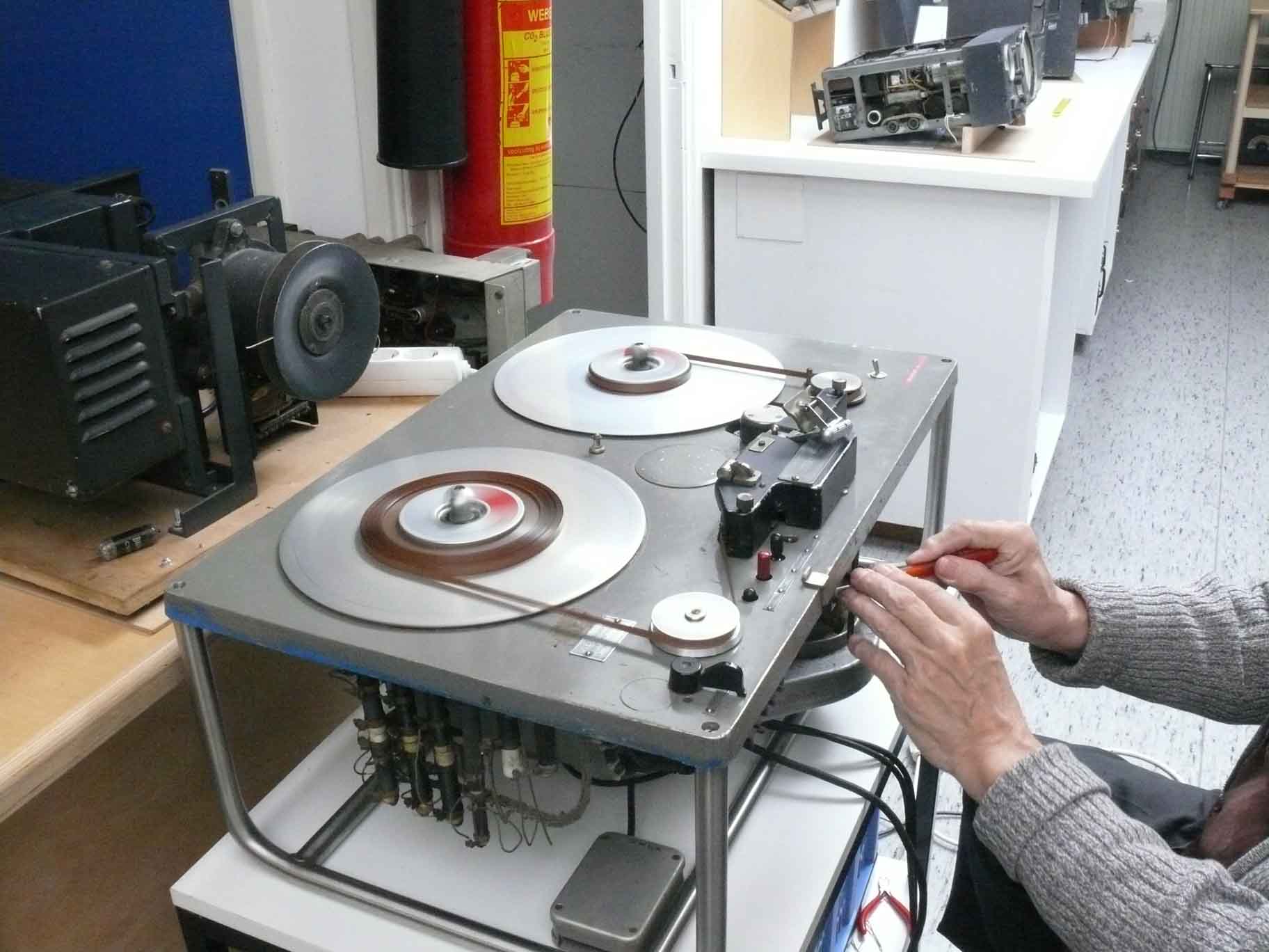
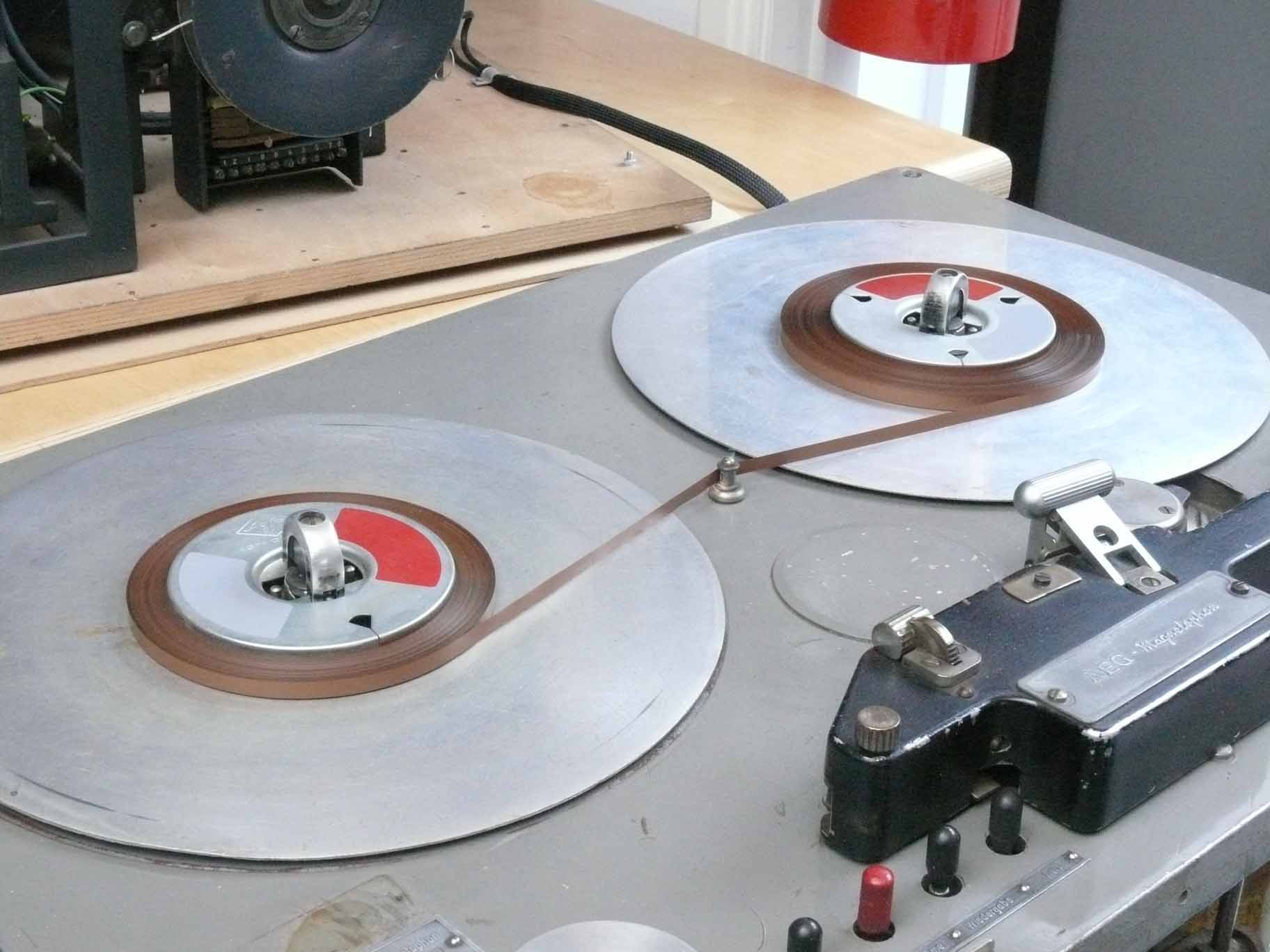
The machine starts to function for the first time in our museum
Please watch the fuzzy red field of the tape core.
On the left-hand side of the machine a set of high power resistors are visible, which are radiating quite some heat. Hence, care should be taken, because these likely are galvanic connected onto the mains. For safety reasons, the system being operated by means of a variac separating it galvanic from the power line.
On 3 November 2013
At the rally of the 'Dag van de Amateur' held in Apeldoorn yesterday, I found the covering-cap to the well known Tuchel-connector, which is used in the Magnetophon for connecting 220 V onto the mains. I bought it fit with a three row multi-pin connector, but luckily the two row female fits also into it.
Dick wanted to have this safety provision, but after having fit the cable onto it, it proved that they might never have used one.

The situation shown where the metal safety-cap have been adapted a bit
This is what I encountered unexpected
The solder-tag is blocking the full insertion of the Tuchel connector cap
By the way, Tuchel a prominent German connector manufacturer was later bought by Amphenol, they now acting as Amphenol-Tuchel

My simple solution as to make fitting possible, without risking safety
On 15-19 January 2014
Dick Zijlmans and myself inspected the two starter capacitors prominently visible.
Measuring them I do not trust as it is hardly possible to read-off from a Wheatstone bridge what a component is doing under working conditions.

What we need are two 2.5 µF starting capacitors
We ordered in the meantime two modern replacements which are nowadays so-called round types. Special provision is to be made and these will be mounted aside the original rectangular ones. As to keep the general vision as it was before.
On 16/17 February 2014
After a rather long break I would like to starting up again our Magnetophon project. Although, I first have to accomplish the still rather resisting G-Schreiber project. Maybe closing it ultimately.
The idea of investigating the motor capacitors engendered after an e-mail exchange where someone suggested: look for the electrolytes. I first wondered, but then I realised having recently seen a Siemens paper of 1939 where they also deal with bipolar electrolytes for motors (Anlaufkondensatoren). The ones we employ are from, say, 1947, a bit old for an ac driven bipolar electrolytic capacitor isn't it?

As to maintain the original look the two original motor capacitors being kept in place and the two new samples being mounted where apparently the third once was fit. This one being most likely removed by our Belgium friend who once donated this machine to our Foundation
A quick test shows that winding-up in either directions goes smoother than it previously did
Considering the way the tape is being wound, we may guess that when it runs guided via the tape-head arrangement that all will perform even better.
On 19/20 February 2014
Dick started with working on the Magnetophon project again.
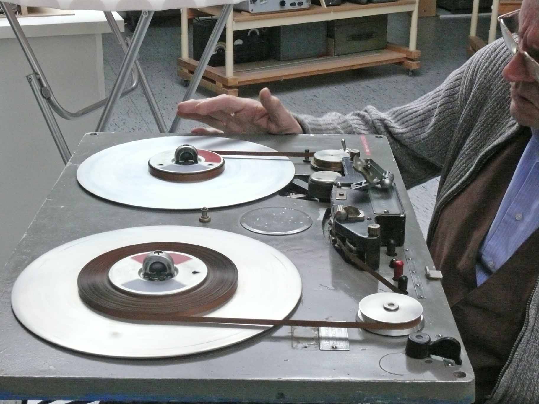
Dick Zijlmans dedicated extra attention to the tape-spooling
It was discovered that the first few few metres it ran correctly, but suddenly a change in the position of the tape occurred, causing the tape winding up became irregular.

After having cleaned the tape guiders in the tape-head, Dick watched especially the moment the tape transport height changes
He thinks that we should take a closer look at the way the most right-hand side tape guiding-wheel is changing its vertical position. How and why is yet not understood.

Another concern is the state of affair of the roller-bearing which is pressing the tape onto the capstan
It was found that it runs extremely light with some noise. Dick removed the assembly and we took the two bearings out. Cleaned them and re-lubricated them.
Our first aim is finding out why the tape does not run entirely correct. We both guess, that this might be caused by a combination small shortcomings.
To be continued in due course
Reported by: Arthur O. Bauer
Please consider also the continuation page: The magnetophon starts running
Please continue, or proceed with: Magnetophon patents
![]()