
Exhibits details page 3
It has become clear to me, that Exhibits details page 2 is becoming too much over loaded. Especially for those being dependant upon slow internet access. As is also occurring for those having wireless internet.
This page is also including some of the previous Exhibits details page 2
Started on 22 July 2011
State of affairs: 12 January 2014
Starting with some photos of the previous page 2
For your own convenience, we would like to advice you to use the search mode
for Windows users: Ctr + F
and for Mac OS X users: Cmd + F
Entre your particular search word and all those words inside this document will be successively shown
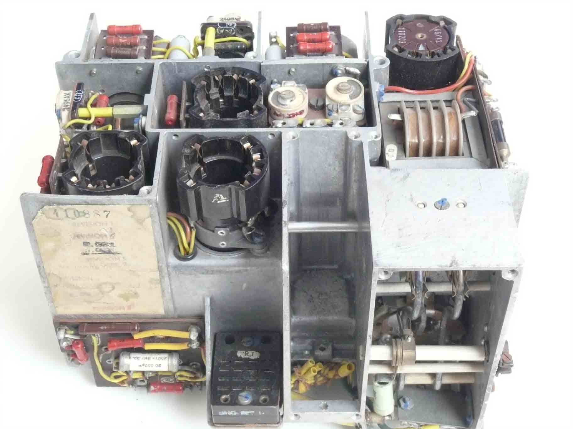
Detailed photos of what is inside an EZ6 receiver
(1)
EZ6 combined with PT10 or FuG10, making it a FuG10P
The shown system is to be used for long and medium waves. This automatic DFing system was widely used in German long distance aircraft.
EZ6 was designed by Telefunken, and is a wonderful piece of technique! The next shown set is, however, not in all respect complete. Its function is only to show what it is about.

EZ 6 inside view. Its compactness is striking!
Please notice the centre holes in some of the trimmers. The purpose is that it becomes possible to tune the circuit inductively as well as by means of the trimmer capacitance. Similarly was done in the Köln E52 receivers, but EZ6 is by far more compact!

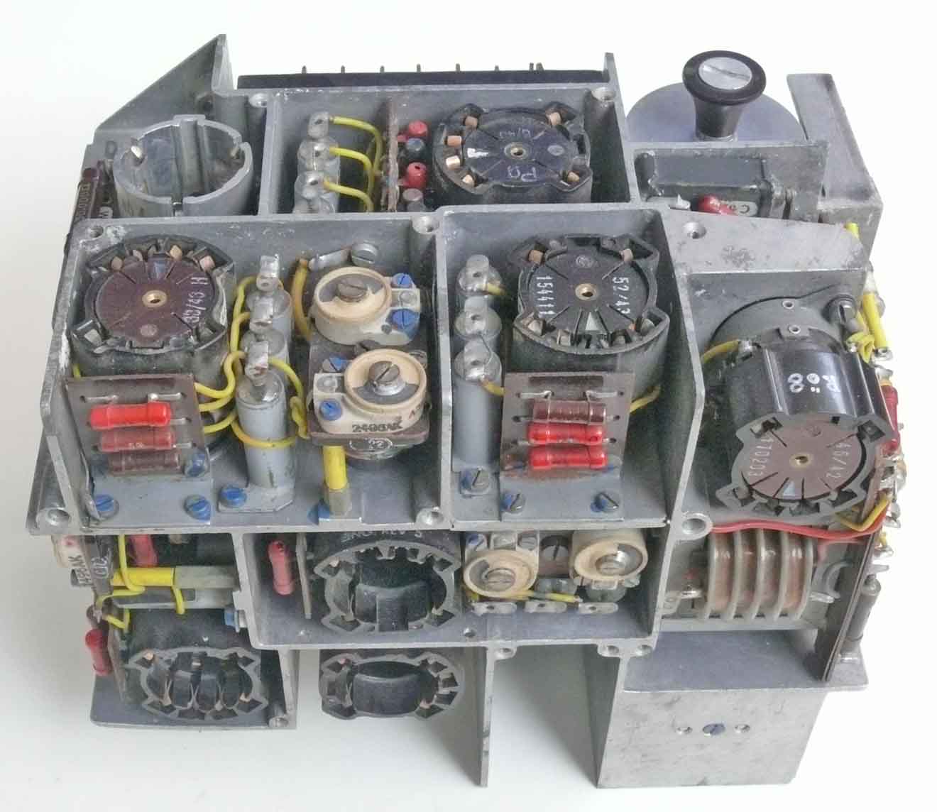
EZ6 shown from a slidely different angle, as to get a better idea the way it is constructed

EZ6 shown from a different side

EZ6 from the BFO side

EZ6 shown is what is behind the front panel

EZ6 shown is the rear side

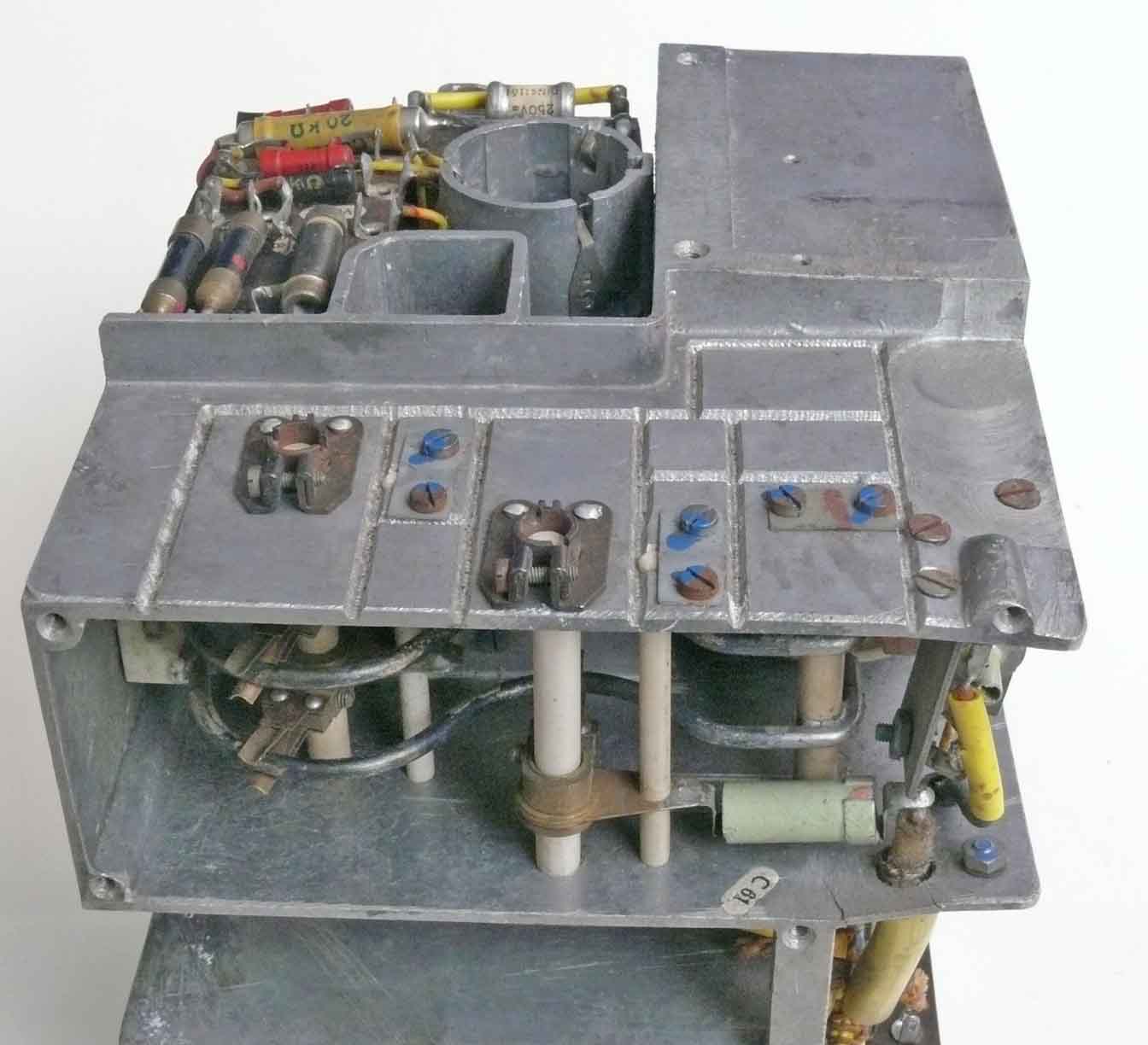
EZ6 oscillator-temperature-compensation section in detail
Its aim is to keep the local oscillator of the EZ6 as stable as possible under aircraft environmental conditions. The stabilising circuit is mounted at a ceramic plate, using already printed circuit interconnection technique.
The aim of connecting (wiring) many capacitors in parallel is - that the arrangement is to respond faster on changing temperature. In fact the surface of the capacitance is divided over the number of Cs involved, thus introducing a capacitance having a larger surface. The system responds swiftly but also not abruptly.

The motor of the antenna polarisation and receiver out is just being pulled out
Its function is that the phase of the DF loop and the audio output is being switch synchronously. This makes it possible to indicate whether a radio beacon is left or right of the virtual antenna direction. The auto-DF-mode is designed as to tune at signal minimum. Please notice the HF pot-core, these cores where later well known in ferrite cores. This type is, however, made of dust core.

The integral EZ6 antenna-switching-motor (GAF stock number Ln27390), as is shown in the previous picture
Motor 24/1,7
Gerät Nr. 19 5732A-2
Hersteller det?
Serial number 0408
This time we would like to continue with some telephone related devices
(2)

Siemens & Halske 'Viererabschluss' type Rel mswd 11a

Rel. Sk VII E 26/14
'Sk' might stand for: Schaltskizze (production drawing number)
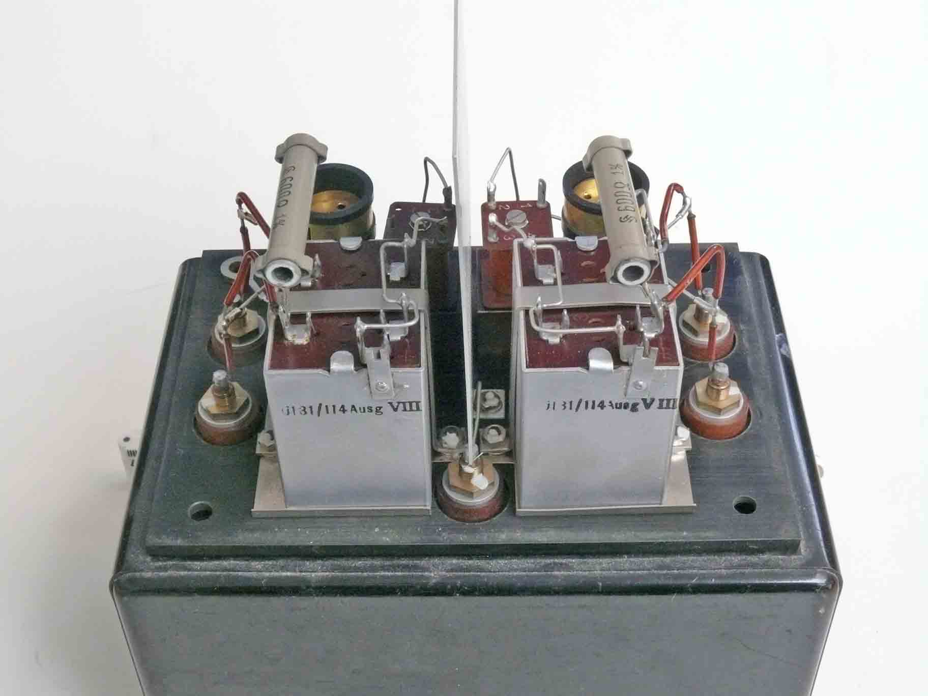
The 'Viererabschluss' module from inside
This type is kept symmetrical by means of inductances.
A Vierer circuit is also known as a 'Phantom' system.
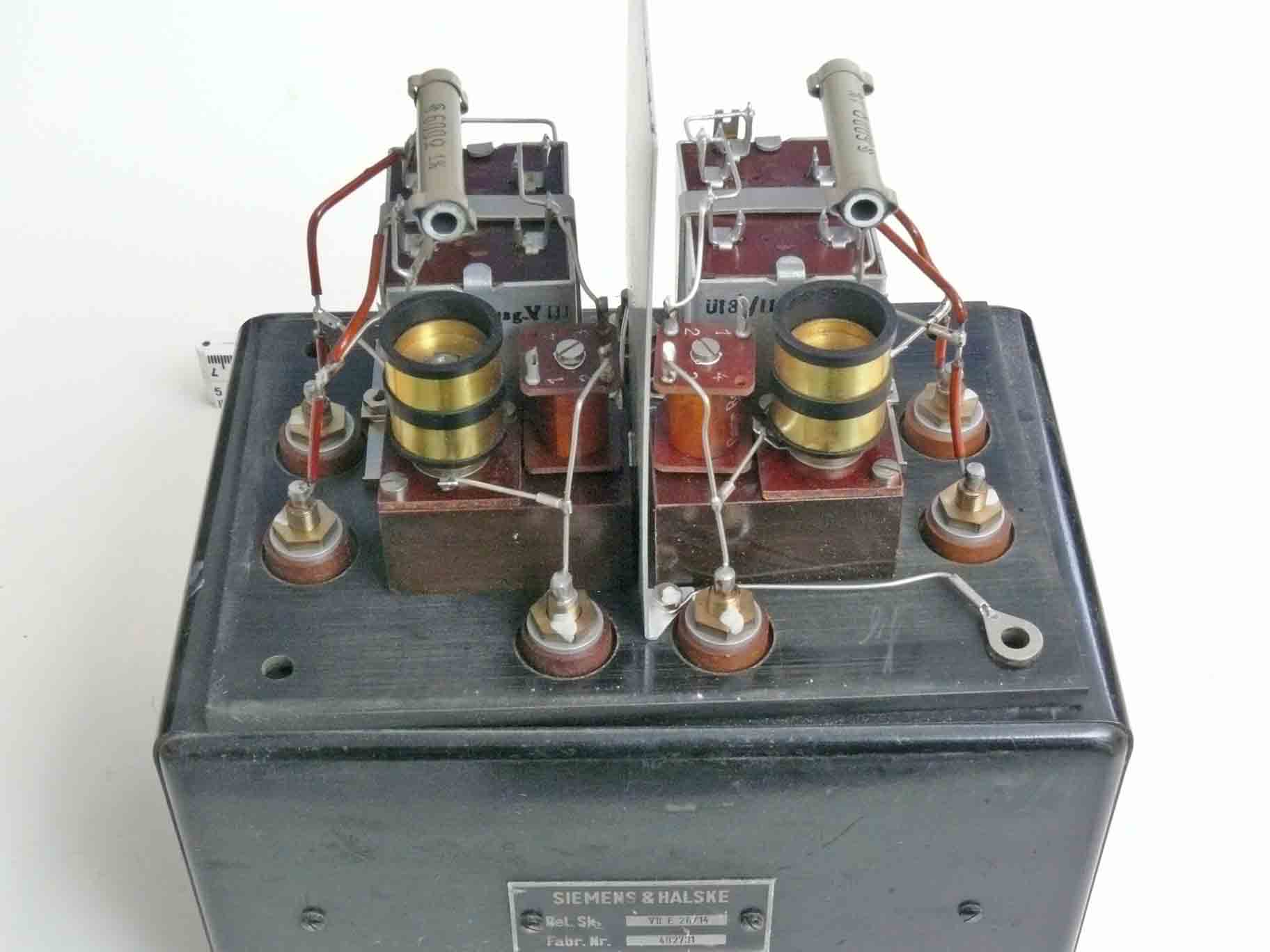
The two brass cylinders belong to the symmetry-trimmers
Telephone systems used in between telephone exchange offices a four wire technique. (only the line between the exchange system and the consumer is constituted by a two wire technique. A special fork- or hybrid-circuit is then splitting the two wire line into a four wire technique. Of course, this technique is also transferring a four wire signal into a two wire line pair) Two wires for the incoming signal and two wires for the outgoing path. Each cable pair is optimally balanced against ground. To exploit the lines optimally each cable pair was also used in phantom mode. Exactly at the centre of a cable pair a signal was added which travelled in common-mode. Thus in each cable pair equal signal current was flowing. At the cable end the signal was symmetrically, thus exactly centred an fed onto a separate telephone circuit (even capacity against ground or earth). It was, however, necessary to use two cable pairs as to convey a two wire signal. Please notice my paper on Line communications
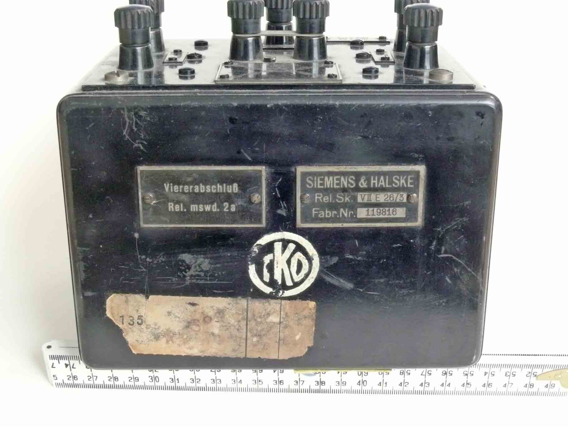
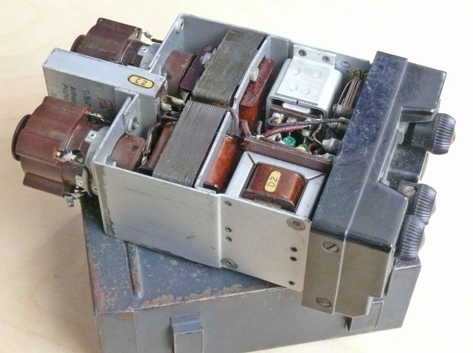
Viererabschluss Rel.mswd. 2a
Rel. Sk. VII E 28/3

Stamm 1 and Stamm 2 are both connected in the centre of a single cable pair

The centring is accomplished by means of two special calibrated wire-wound resistors

The two nickel tubes constitute capacitive trimmer, as to adjust capacitive symmetry

The principle of artificial phantom technique
Stamm 1 is sending from 1 towards 1a; Stamm 2 is receiving the message from 2 a towards 2. It looks like that symmetry is accomplished by means of a centre tap. This might sometimes have been the case, but the black boxes above are, I guess, devices that can create phantom circuitry fully externally. Either by means of a pair of special inductances or simply by means of a pair of precision resistors. In both cases a capacitive fine adjustment was necessary. We do not realise, that a classic telephone line is very sensitive to un-symmetry. Try yourself to touch with a crew driver one side of the telephone contacts and you might hear that hum is coming up. Pointers are showing the trajectories and also that each line pair is carrying phantom signals in 'common mode' whereas the voice signal is acting as an a.c. current signal.
Field line interception
(3)

Drahtlauschempfänger klein
The small portable unit was used for telephone field-line interception.

D.L.E. (kl)
1869
dlj/42
It was in 1942 delivered by: Opta Radio A.G. Leipzig

D.L.E. (kl) bottom lid opened. Visible two RV2,4P45 valves (space charge valves)
The same battery type was used for filament as well as anode voltage. Had periodically to be interchanged. As the filaments are consuming more than does the anodes.

DLE (kl) openen
D.L.E. (kl) shown from a different perspective

Although, this set was accepted in 1942, the date stamp of April 1941 shows that it took some time before all was finally finished
An interesting option was, that it was possible to tap onto telephone lines without notice to the enemy. For this purpose the set-loading-impedance was > 500 kΩ . This in the environment of say 300 - 800 ohm line impedances, may be regarded being ∞ (infinite). Operators will not hear the expected (famous) click at their line.
Next we focus on the main module of FuG25a
(4)
FuG25a
The main module of the German aircraft IFF is consisting of a receiver as well as transmitter. Both interacting as a signal transponder. Please consider the FuG25a manual. FuG25a (D.(Luft) T. 4010 and its Schematic in A2 size. (please notice that it is possible to print the latter schematic in A4 size with the pdf option "print what you see")
FuG 25a IFF transponder

FuG25a

FuG25a
On the left hidden in the module the transmitter valve LS50
FuG25a
The typical groves in the die cast frame is to destruct immediately as soon as the set is to be blown up. As to prevent the enemy to determine its operational (transmitter) frequency.
Please notice the blue colour paint dots, which function is to lock screws and nuts together. In most cases they used instead grey colour paint.

In the upper section we see the Lecher-line like transmitter tuning
It is clear that the FuG 25a photos are showing that the module compactness is quite impressing. It is also evident, that the LS50 and RV12P2000 concept is allowing 3D way of apparatus design.
New since 22 July 2011
(5)
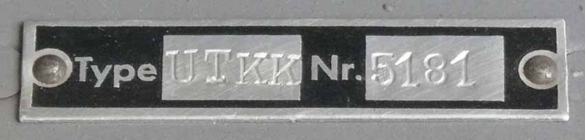
Rohde & Schwarz (PTE) Diode-voltmeter type UTKK serial number 5181
Please notice, that the Na-Liste is showing a different kind of pick-up-head!
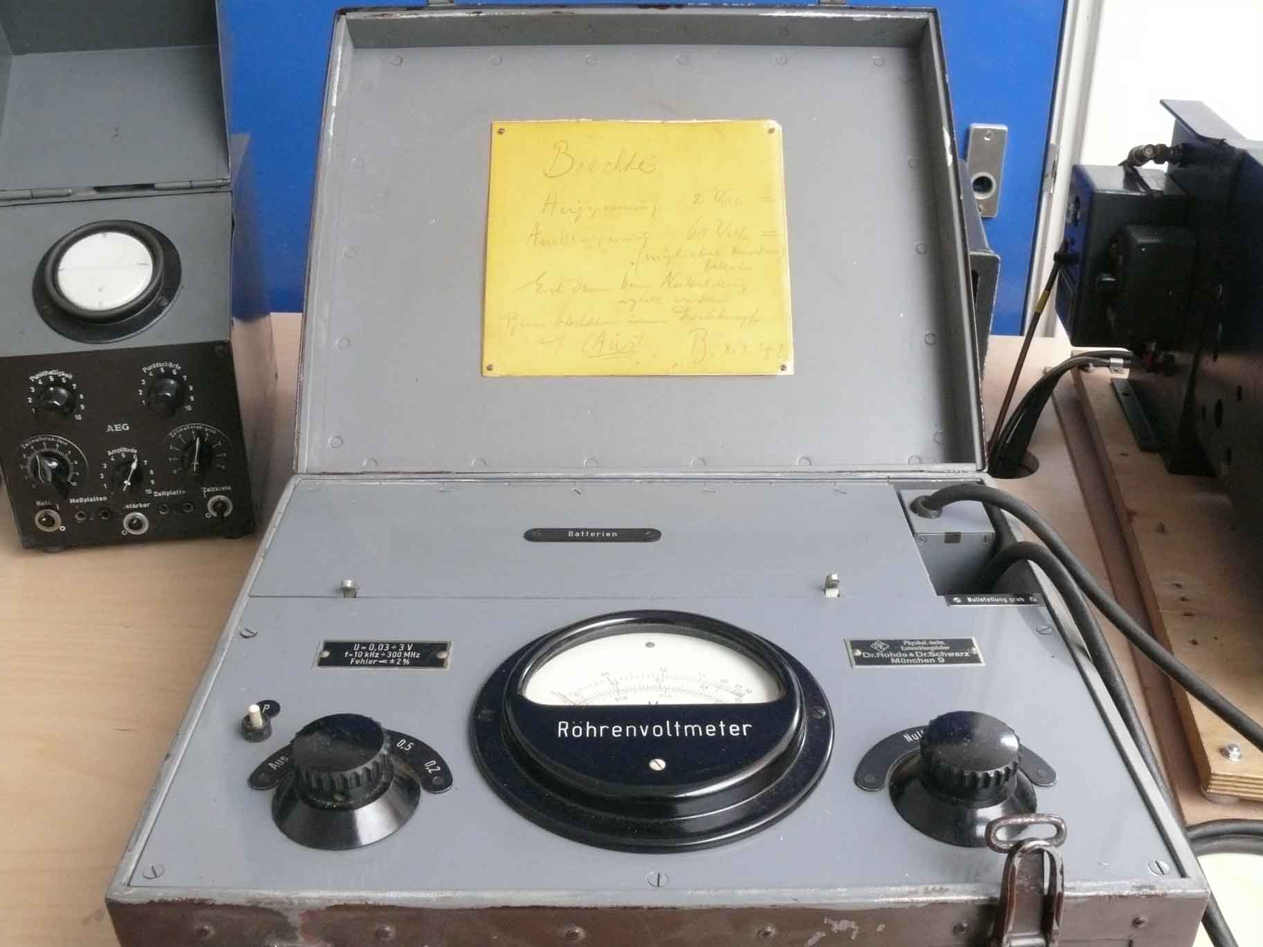
UTKK box open

Please notice, that the Na-Liste is showing a different kind of pick-up-head!
This information label tells us:
That the label-date is 8 September 1942
Filament voltage is 2 V and anode voltage is 60 V

Measuring range 0.03 to 3 V; between 10 kHz and 300 MHz accuracy < 2 %

Battery compartment open

The diode-head
The small button is to activate the build-in diode
On 16 August we have continued with:
(6)
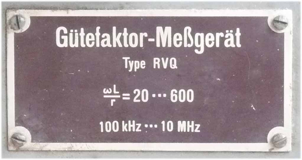
Gütefaktor-Meßgerät RVQ
Q-factor measuring apparatus type RVQ made by PTE (R&S)
100 kHz - 10 MHz
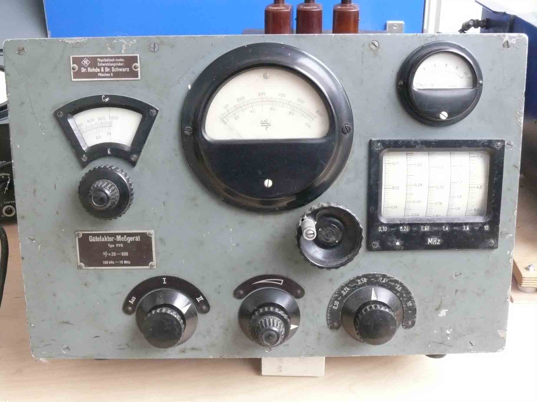
Front panel of RVQ

The to be measured Q of a coil is connected onto these two contacts, being on the left hand side of the apparatus

RVQ, rear panel opened
I guess, noticing the valve types being used, that its concept might go back to about 1937/38

The HF section of RVQ
They might have used KB2 instead of AB2 because of its internal capacitances
On 29 September we continued with newly obtained artefacts
(7)

Test receiver generator DXE 502 G01(serial number 33956)
Production code 'bya' tells us that it is a Gema product.
This set is known as X-Gerät
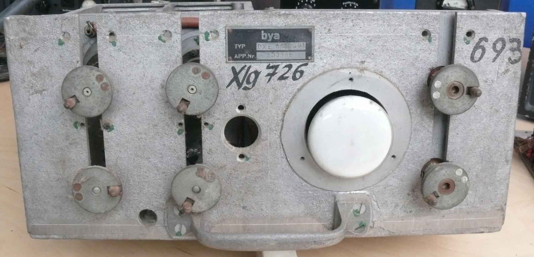
Front panel of: X/g 726 on the far right 693
As to prevent from overloading this page; please view the page with more detailed descriptions Gema X-Geraet
Please proceed with: Exhibits details webpage 4
Owing to the fact that this current webpage is becoming too much overloaded we have created an additional webpage number 4
Finally our:
Berlin radar considerations
This Berlin related contribution does not entirely reflect what we actually possess, but is attached as it forms a subject of which we have some parts, like the Berlin PPI display unit SG224 and the pulse forming network LK1 (Laufzeitkette) and the pulse step up transformer.
After I presented my paper to the CAVMAG 2010 conference held on 19-20 April 2010 (The German Wartime Struggle to catch up with Allied Power Magnetron Technology), I discussed with Hans Jucker the properties of the pulse-forming-network type LK1. Which actually must have been a copy more or less of the same circuit found in the remains of the Rotterdam apparatus (H2S early version). He soon calculated the electrical energy stored in it. Its title is: Modulator of the German Berlin microwave radarset (equals GAF type: FuG224 or Berlin type A). I obtained these parts about 1980 from late Ebbe Peedersen of Denmark. Putting all facts together, I guess, that it remained from dismantling of a FuMO81 radar set which was captured by Danish authorities in 1945. Whether with or without British approval, I don't know. I obtained these components as it fitted to my future strategy. Although, I myself never could have foreseen that it ever was possible to swop the very rare Berlin radar PPI display unit (SG224). And showing it this way!
We very much would appreciate to find other Berlin radar modules or pieces

Pulse forming network type LK1
Please see for its circuitry Hans Jucker's paper
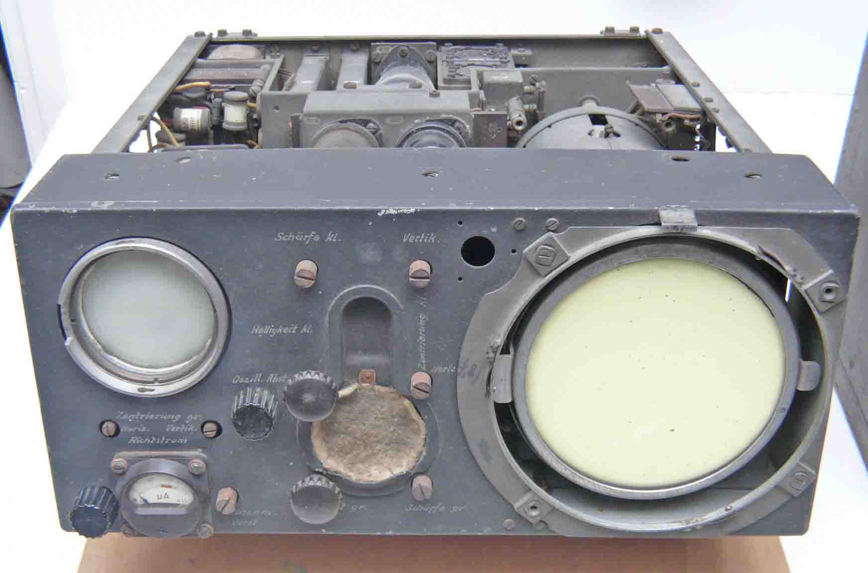
Berlin PPI display module type SG224
This module was obtained from Britain, some years ago
The following Berlin radar related photos, is not part of our collection, though being meant as to show how some modules look like

Berlin A type transmitter/receiver front-end

Feld II of the Berlin A system (serial number 391)
The upper module is like the previous photo, the lower section contains the modulator. In contrast to British H2S, it does not have the pulse forming HT section integrated as this was by German redesign an integral part of the transmitter section, which is from a technical point more appropriate, as the 10 kV pulse signal does not have to be fed by means of an external HT cable.
Feld I

Feld I (module 1)
The timing (waveform generator) section including the IF stage. This module is the top one left on the last photo

VK224
Control box of the Berlin radar system, its main function is to interconnect the system wiring incorporated in a single unit
Some time ago Horst Beck did send me the next photo
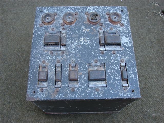
VK224, apparently the Naval version, Thus representing the same function as the previous module
This device was offered to Horst Beck some years ago though, he has rejected it (maybe too expensive?)

Berlin radar, mounted at a frame. Most likely of navy type (FuMO81 = FuG224) This type of mounting often was called: Prüftafel (Testing rack). I guess, it would have had then designation PT 224
Although, the text on top of the mains switching box indicates 230 V 50 Hz, this might have only controlled the voltage convertors for 80 V 500 Hz, like was used for H2S as well. Curious is, that the Germans, like in most other continental countries used 220 V 50Hz. Probably tailored here for British circumstances.
We would be very pleased to get any kind of feedback from those who have or can add additional information.
Please notice our e-mail address up this page
![]()
Please type in what you read
Arthur O. Bauer
Please notice also our: Exhibits details page 1
Please continue with, or return to Exhibits details page 2
Please continue, or proceed with: Exhibits-details page 4
Please consider also our new Würzburg repairing survey: Wurzburg report
Concider also, or go back to: Archive displays
Consider also, or proceed with: Exhibits registration
Back to: Exhibits new
![]()