
Elefant radar transmitter
Elefant-Sender
Illuminating transmitter to a German wartime Bi-static radar system
Please notice a review of the following document
Ingo Pötschke did send me, some days ago, a few pages concerning a document, which had been made to investigate the state of affairs on the first Elefant radar transmitter (Bi-Static technology, K-H), which just had been delivered by Telefunken. From the text it is impossible to discover whether it was under investigation by a German military institution or that it was being held at another Telefunken branch (test site?). It is, regarding the background of the pages, generally speaking an AEG project. However, in 1943 AEG owned 100 % of Telefunken and this branch had 'the' expertise designing these kind of systems. During wartime it is not always clear who actually built what system. In pre-war days, most Telefunken systems had been constructed by Siemens or AEG; as Telefunken by itself was more a designer than a producer. Due to this, Telefunken made often a fiscal loss, as the two share holder might have charged too much for their production facilities. Resulting in a better than normal performance of AEG and/or Siemens (S&H and/or SSW). Please consider the Radio Mentor notice on the split of ownership coming into being in 1941.
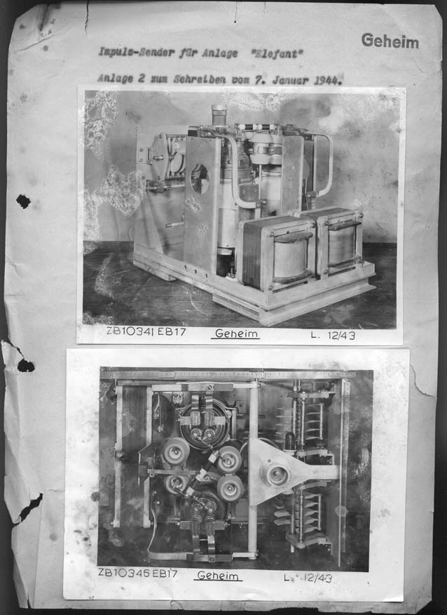
A brief report by Dr. Schilp on request of Mr. Stepp (Dipl.-Ing.), date 7 January 1944
The attached document photos were showing strong signs of deterioration (fungus)
It explains that Telefunken section EC17 had built and tested the transmitter to the Elefant radar system. It is mentioned, that realising the task was accomplished within 8 weeks and was handed over on 21 December 1943. What I didn’t know yet, is the Elefant transmitter equal to the one used in the See-Elefant system? Mr. Stepp belonged, by the way, to Telefunken section EC2.
What can we learn from this document?
Mr. Brand headed (Ltg.) Telefunken section EB
Mr. Haase was engaged at section EZ
Mr. Urtel was of section EC
Dr. Rothe was connected to section LH
Mr. Stepp of EC2
In the header is also mentioned a Dr. Sommer
My wife reviewed her Photoshop work again on 15 August 2014. Her first close look was focussing on: what is the actual content within the red stamp?
EB 1 is clear. The signature might point to Rot 4 (RCT 4??), Rothe is not very likely.
What fixed text is incorporated? After very detailed consideration, viewing the original not yet modified file copy, it might mean: xxmittlerer Leistung. Medium power sounds strange as we deal with 330 kW pulses. But Telefunken dealt with far higher energies. Thus, medium is not un-likely.
Mr Schley and Mr Kennel of Telefunken section EC2 had been directed by EB17 to manage the construction and its testing: Herr Schley und Herr Kennel von EC2 d?urch EB17 für diese Aufgabe zur Verfügung gestellt worden und führten den Bau und Erprobung des Senders nach unseren Angaben im wesentlichen alleine durch. Further on in this document they mention that the antenna tuning was designed for wavelengths of 8 to 9 m. Die Anodenkreisabstimmung des Senders erfolgt mit Hilfe eines einfachen Schleifvariometers. Parallel zu diesem liegt eine feste Spule mit zwei Windungen, an die der symmetrische Antennenkreis angekoppelt ist. Anodenkreis- und Antennenkreisabstimmung, letztere mit Drehkondensatoren, sind für eienen Wellenbereich von 8 - 9 m ausgelegt. It is also mentioned that he (Dr. Schild) has been informed that both men have accomplished this task solely. ... und führten den Bau und Erprobung des Senders nach unseren Angaben im wesentlichen alleine durch. However, although I cannot read it, there might have had someone comments on to this statement, which is written down vaguely with a red pencil.
I cannot judge the figures in respect to the data on See-Elefant at RØMØ of, say, June 1945, as 8 m is equal to 37.5 MHz and 9 m is 33.3 MHz. Although, this is not too far off the one used in the See-Elefant system at RØMØ. Where they operated about 30 - 32 MHz in most cases. Nonetheless, it should have been possible to operate the system between 20 - 40 MHz. A fact is, that both used RS720 transmitter valves and that both schematics are about similar.

The schematic of the See-Elefant transmitter as it was attached to the T.R.E. Post Mortem report of 1945. This TRE report dealt with the See-Elefant station on the Isle of RØMØ
Comparing both documents, one does not have to be an expert to recognise their similarities. The major exception is, the parallel variometer which is part of the first document and that is missing in the RØMØ document. I don't wonder, as there are apparently more discrepancies in these kinds of British TRE documents. As we have already noticed in the Klein-Heidelberg page - many (maybe most) British post war reports are lacking inspiration to scientifically approaching enemy technology.

Viewing the Elefant transmitter from the top (cover being removed)
Please click on the photo as to get the version without symbols
Please consider also the Elefant schematic (Fig 24)
A and B are both neutrodyne capacitors, preventing uncontrolled oscillations
Both Cs are interconnected mechanically and is to match the transmitter output onto the coaxial antenna cable (Zo = 70 Ω)
Both FCs are fixed ceramic capacitors as to keep the 'splitsator' plate separation sufficiently wide; as: P = U² / Zo → U² = Zo . P → U = √(330000 x 70) = 4.8 kVrms (bursts) at the output (antenna) connector (considering that the coaxial cable is having a 1 : 1 SWR)
H is filament connection of the valves RS720. Rather sophisticated power tubes, which could be fit within a metal cooling block. These 'high' serial numbers must basically have been developed during, say, 1940-42
G is the triode grid. As to lower its 'inductance' two grid leads are being provided
T are the filament transformers
The HT pulse is supplied by the pulse-modulator (Tastgerät)
Don't under estimate the heater consumption of RS720!

AEG Data sheet to RS720 (1957)
Its filament consumption is: 130 A at 4.9 V (637 W)

RS720 dimensions in mm

Udo Radtke was so kind to provide a nice photo of a RS720. I doubt, by the way, that Siemens manufactured these power valves during wartime. Although, it has to be noticed that some of Telefunken power valves were actually manufactured at either AEG or Siemens & Halske. The cooling block might have been a bit different for this occasion
For us interesting is, that according to the specifications the maximum applied HT is 30 kV @ 30 MHz. Which is not fully in accordance with the data provided on the TRE schematics. But is fully in agreement to the data in the Telefunken brief report of 7 January 1944.
Although, not being mentioned is the fact - that the anode connection is very down the RS720 envelope. As there is no sign of an anode-connection in the top-view photo. Please regard the next photo.

Elefant transmitter viewed from the rear side
Please click on this photo as to view the picture without symbols
T is the filament transformer, each one for a single RS720 (4.9 V 130 A)
VT is the variometer tuning as to adjust the anode circuit at the appropriate frequency. The valve anode capacitances (Cak and Cag) are virtually interacting with the anode inductances, and so creating a 'L' - 'C' parallel tuned circuit. Where 'C' is a static valve parameter and 'L' is to be tuned by means of a variometer (VT). System oscillation is actually being caused by the RS720 'Cag' interactions (causing a positive feedback)
Both A marked capacitors are each of 100 pF, which is making in series 50 pF (equal to chain B). 50 pF is a quite high value for, say, 30 MHz though, is likely resulting from the rather high internal valve capacitances, also against ground (tube cooling block etc.)
C is the dual loading C of the antenna output loop (Splitsator)
K is meant for adjusting the coupling between the anode circuit and the antenna output coupling-loop
The filament feeding strips are actually two strips which are being kept both parallel as to minimise its inductance and HF interference as well as to enhance their mutual capacitance (please consider: that the filament leads are directly carrying the HF tube current towards ground). And, of course, this method is also saving space.
The RS720 cooling block is quite well visible, according to the data sheet there existed two types; one for liquid cooling and one for air-flow-cooling. The latter one is being used in this project.
The Elefant transmitter used a prf of 25 Hz and each pulse had a duration of 10 µs. The total transmission time of full HF energy output per second was thus 25 x 10 = 250 µs of accumulated duration. According the given output figure the HF power was 330 kW or 330,000 watts; 250 µs is only a 1/4000 part of a second → 330,000 / 4000 = 82.5 watt/second. The total heater dissipation is 2 x 637 W = 1274 W. The efficiency of a RS720 in class-C mode is, say, 60%. The extra dissipation is 33 W. Making a total of 1274 + 33 = 1307 W. Neglecting the dissipation of the two filament transformers. The heat of the HF components will not be adding much to this figure. Say, 1.5 kW can easily being handled by means of a low pressure air stream cooling. Why have they, nevertheless, employed such heavy transmitter tubes? The solution is quite simple, one need a very 'willing' cathode that is capable emitting within a microsecond up to 18.48 Amps. A RS720 has thus to deliver this value each half of the push-pull cycle. According to the data sheet, its maximum Ia is 30 Amps, and thus sufficiently high for its purpose (whereas continuously it could only deliver 1.45 A @ 10kV). Hans Jucker pointed in a response onto this web page: Please let me correct my earlier statement concerning the pulse input power of the transmitter oscillator. With a cathode emission of 30 amps and a plate voltage of 10 kV the two final switching tubes can in maximum handle 60 amps plate saturation current, therefore the typical pulse input power of the Elephant transmitter seems rather to be in the order of magnitude of 500 - 600 kW. However, if the transmitter oscillator is corrected matched to the load the efficiency by on 30 – 40 MHz may certainly be higher than 50 %.
However, in the context of this paragraph, it should be noticed that the RØMØ schematic (Fig. 24) is apparently having an incorrect HT circuit. We see a series resistor of 1000 Ω between the 33 kV modulator-pulse and the plate circuit. When we consider that an anode current is to flow of, say, 18 Amps, this will cause a voltage drop of 18 kV. A most unrealistic value! Like - as is shown in Dr. Schild report - there should have been instead a HF-choke parallel onto it (please consider the next photo). These are the typical discrepancies in British post war reports; my conclusion:- no one competent has ever reviewed (peer viewed in modern science) this TRE paper.

Side view of the Elefant transmitter (please consider the symbols of the previous photo)
The antenna coupling loop is just visible down the ‘tuning splitsator’ unit (2 x 40 pF variable). Please notice also the choke that links the HT pulse (from the left hand side) onto the centre of the anode circuitry.

The complete Elefant transmitter module (Elefant Sender)
The holes in the side panel are giving access to the various tuning controls (see previous text). I presume, that accessing was only necessary when a frequency change had to occur.
The a bit fuzzy vertical tubular construction is the antenna connector. The air outlet is also visible. This means, that the air flow was coming via the bottom plate of the transmitter chassis. Although, I guessed that the air flow is entering via the bottom plate - there might be another option and that they might have created a tiny vacuum - so that the air flow is entering via the holes in the top section towards the bottom section.
Please bear in mind, that we might look at the Elefant transmitter prototype, and that in the serial type some mechanical changes could have occurred. However, electrically they have not changed much.
The wooden ground plate might function as to keep the module in a horizontal position. When we go back to photo two, one can see that there exist a metal profile (strip) which might indicate that the module is to be pushed on a guiding profile system. The HT input connector is then making automatically contact with the counter-side (female) inside the mounting frame. A rather commonly used technique in those days. Curious on the on hand is that the Telefunken plate would then have faced towards inside the mounting frame system.
After some considerations I have added on 13 January 2011 the See-Elefant modulator schematic. This module has not been part of this document, but was derived from the TRE report on the See-Elefant apparatus found and investigated at RØMØ Denmark in May/June 1945. This so-called: Tastgerät (pulse-modulator) generated the HT pulse that provided the HT onto the push-pull pair of RS720s in the transmitter module. Hence, their doesn't exist a HT in the pause-time, thus in between the transmitter-pulses. It is evident, that the modulator stage has to deliver (providing) the full transmit-power, including its system loss. The HT pulse should have a sound pulse shape, which implies that the HT pulse transformer must be capable of transferring (handling) a quite high bandwidth, as to keep the transmitter-pulse having sharp edges. Don't forget, that the pulse amplitude is about 33 kV! Rising from 0 to 33 kV within say a single micro second is isn't an easy thing, as we have seen that during about 10 µs an energy content of 330 kW (350 kW according the TRE report) is to be delivered. The LS300 driver valve onto the pair of RS720s in de modulator stage is a special Telefunken development, and was also applied in the Mannheim FuSE64 and, maybe, FuSE63 (Mainz) radars.

To reproduce a sound schematic it was necessary to clean-up the drawing though, also correcting the apparent errors
Please click on the schematic as to open it as a pdf document. Printing it, one can use the helpful option in Acrobat Reader by which means it is possible to print what you see at the screen, even when its format is exceeding your printer/paper size! You only have to select this printing option.
On 18 January Hans Jucker kindly sent me his considerations (reflections) on the aspects of the by the Elefant-system distributed power in conjunction with both the transmitting- and the K-H antenna arrays. Please consider also our two contributions: firstly Hugh Griffiths recent paper on Klein-Heidelberg and my technical reconstruction of the Klein-Heidelberg bi-static radar system. Hans Jucker is especially considering the power distribution of the huge Elefant antenna array - the radar equation and the Klein-Heidelberg antenna array. I consider this brief contribution worth to be made public. Some reflections on ELEFANT Radar System
My wife Karin has done a great job in cleaning up the sometimes very poor photo quality of the pictures. Sometimes she had to make a compromise, as occasionally enhanced cleaning will also cause fading of details. Comparing both - the original document and what was finally accomplished, one must say: Chapeau bas! With some thanks to the abilities of Photoshop CS5! Please click here as to view an example of what it originally once had been.
Please continue with, or go back to: Klein-Heidelberg page
Go back to, or proceed with: Handbooks papers and product information
![]()