Bouw Radio Zendstation Malabar
Album pages: 27 - 28 - 29 - 30* - 32 - 33 - 34 - 35 - 36 - 37**
*Apparently page 31 is for what ever reason missing, and should be later scanned and fit onto this webpage.
** Please consider that the photos 36 and 37 do share something
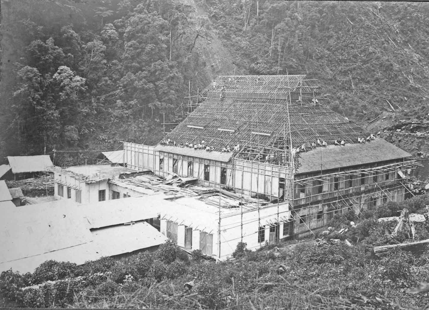
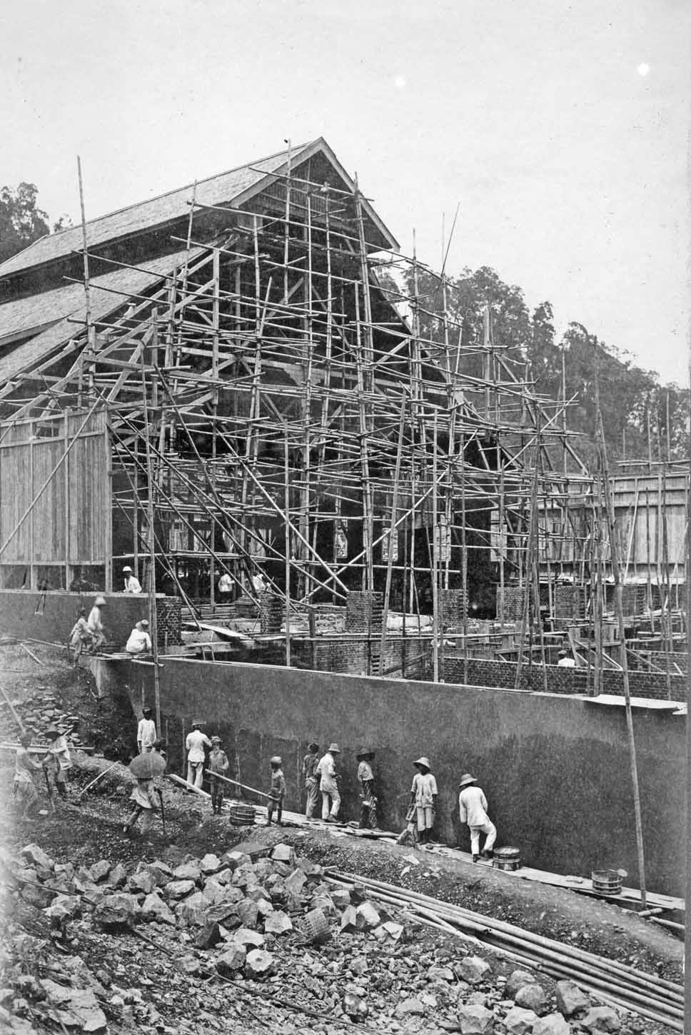
Page 27
Januari 1921
Januari 1921
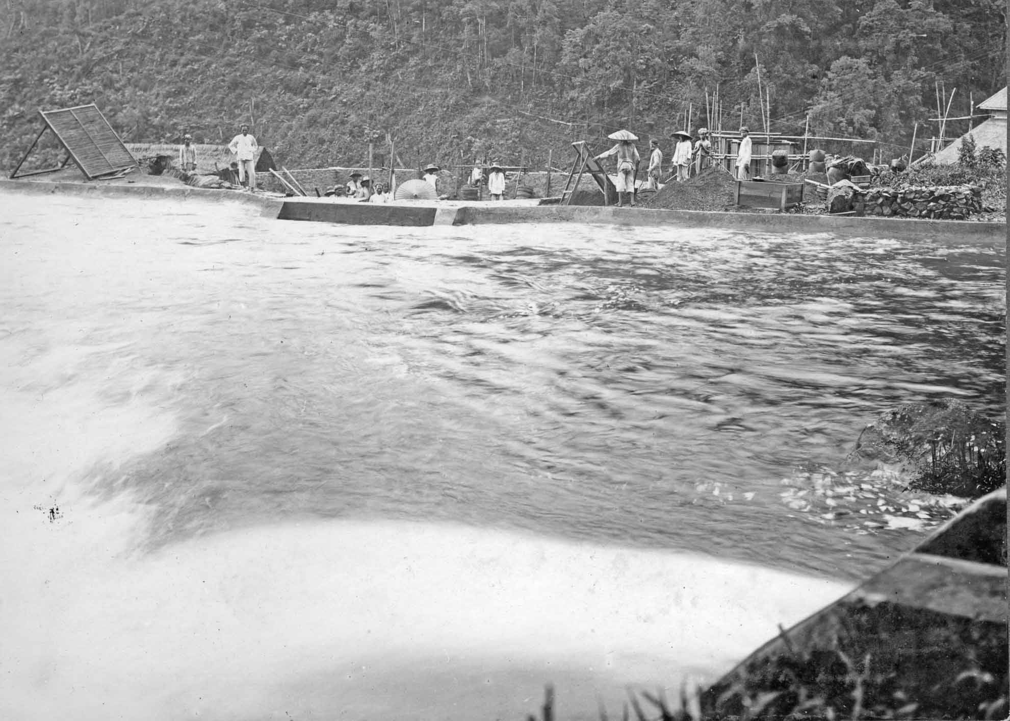
Ventilatie openingen
The Indonesians are building most beautiful and ingenious bamboo constructions, even rather complicates ones. They are real masters of this art. The roof tiles might have been made of 'iron wood' a natural product highly resistant to a tropical environment!
Januari 1921
Working on the roof of the main station hall
Februari 1921
Have they started building the Telefunken transmitter space? This attached hall was later integrated into the Radio Malabar complex. It was against Dr. de Groot's whish, but the Dutch Government forced him to implement the 'Machinezender' in to the Radio Malabar station concept. The Telefunken transmitter was a very good complementary system. It definitely was more reliable than the big Poulsen Spark-Gap apparatus; which demanded much more maintenance and care.
Page 28
Deel grote hal klaar

Februari 1921
We are looking at either the upper or the lower coil housing. Klaas Dijkstra designed the upper coil, the lower one is dealt with further on in this album (but not yet on this webpage).

Februari 1921
The two white quarters in front attached to the main station building are both the fundaments for the future two wooden antenna-towers. Inside the towers were the antenna loading coils.

Februari 1921
Deel grote hal klaar
The photographer was standing at the western* side of the building. The rain clouds are sweeping from the Bangung high lands (planes) up the Malabar mountain slope. Please bear in mind, that humidity reached often 100 %. Although, being in a tropical country, during the night at 'Malabar' it could be below 0° C.
* Please notice, that the four compass directions (quarters) are only meant to be rough estimations
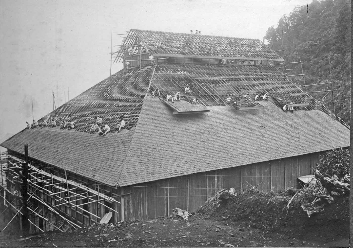
Page 29
Februari 1921
Fundatie grote boog
When you look closely at the already mounted lower coil housing, the first photo on page 28 must be the same device. We know that the lower coil section was part of the HF tuned circuit. The arc inside the spark-gap housing constitute a so-called: negative resistance. The higher the voltage across it the lower its equivalent resistance and thus its across voltage. Hence, not obeying to Ohm's Law. What it actually does, the negative resistance can neutralise the existing loss in the transmitter system. Similar effect is also taking place in the electrical arc-welding process.
Page 30

Februari 1921
Waterontledigingsapparaat
An apparatus for separating oxygen (O) and hydrogen (H).
Hydrogen was the environment in which the Poulsen Spark-Gap operated. It was very convenient to produce hydrogen locally. Its application was not without danger as you can imagine. Sometimes explosions occurred.
Missing page 31
supplemented on 3 July 2014

Date not known
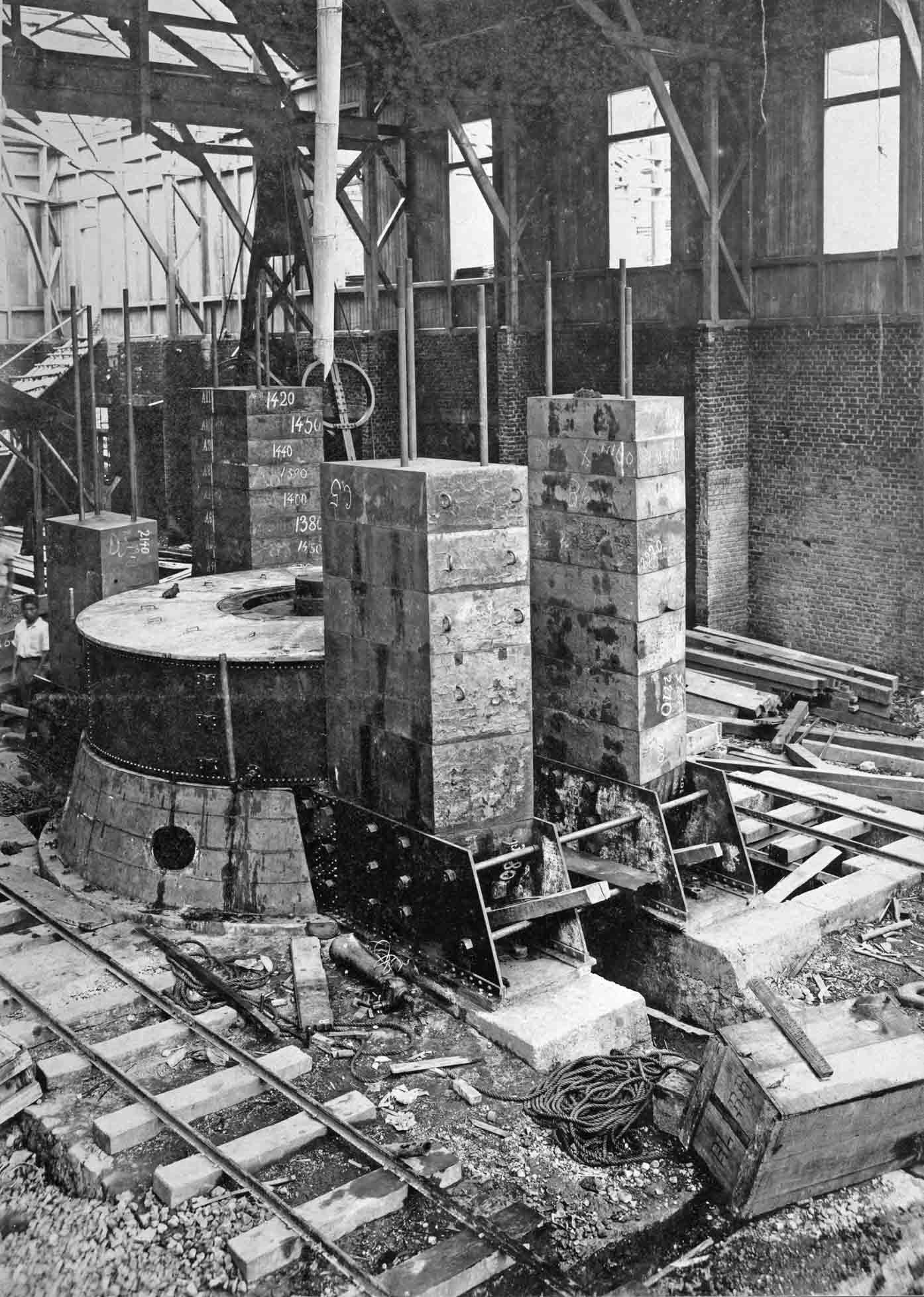
Schakelpaneel
Switching panel, where and when this photo once was take we don't know.
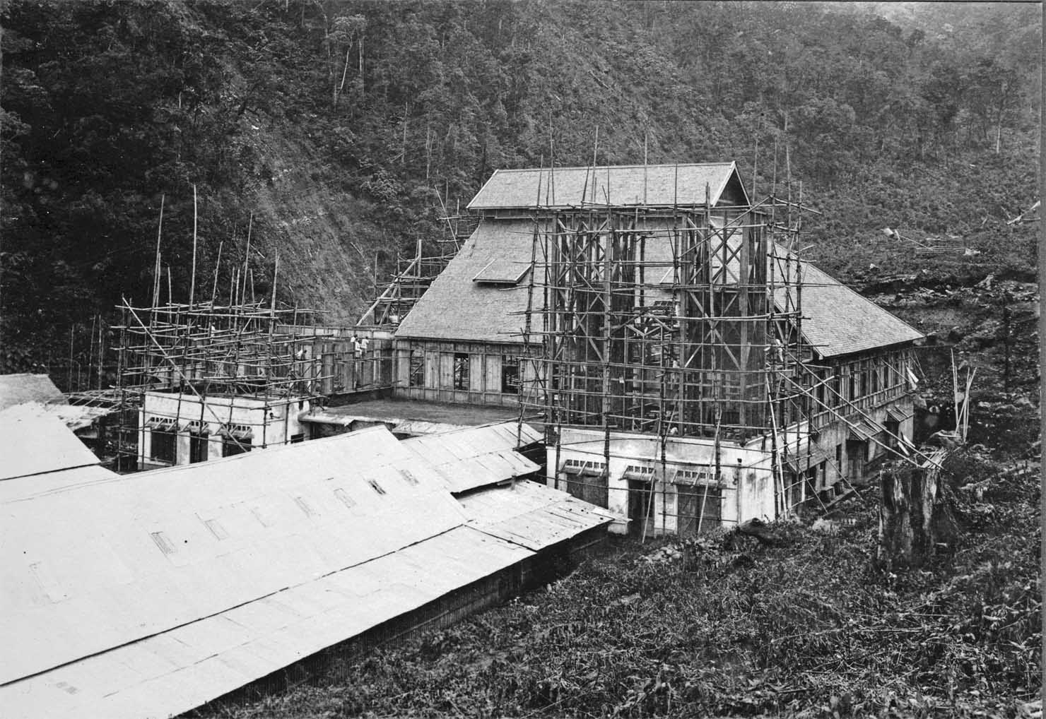
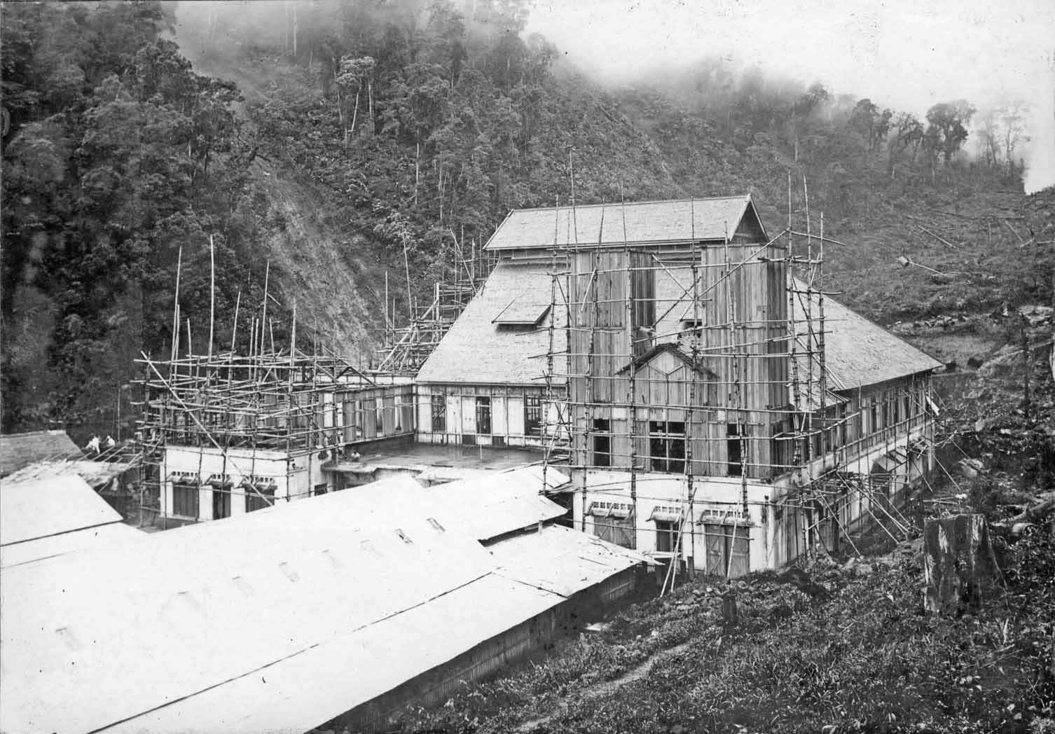
Date unkown
Viewing the front section of the main station building
Must be quite early as the inner structure of the attached Telefunken transmitter hall was still in a premature fashion.

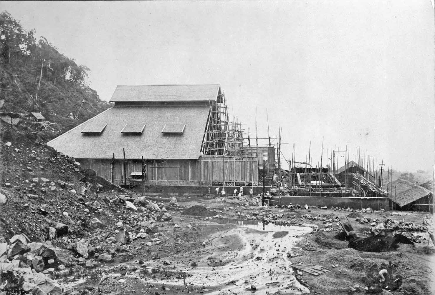
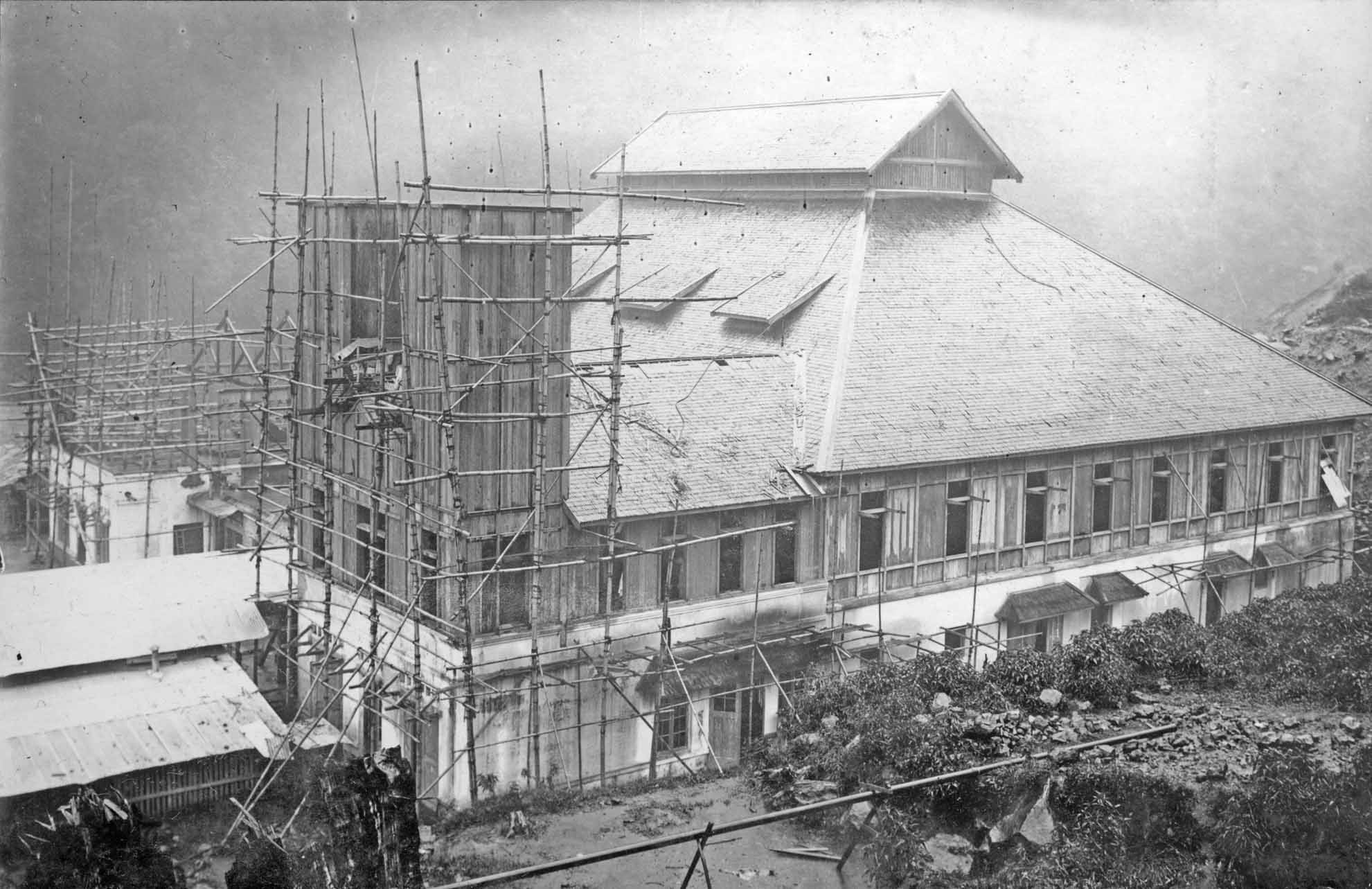
Date unkown
Viewing the main building roughly from the west side.
Directions for this album given only roughly.
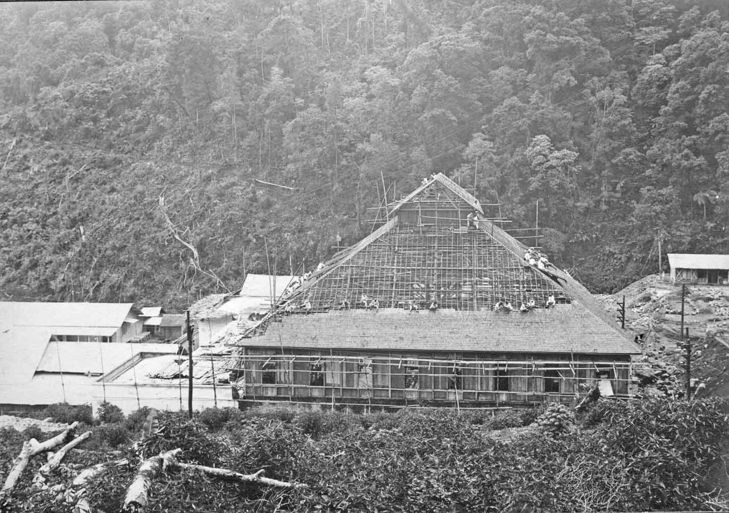
Page 32
Zyaanzicht grote hal
Februari 1921
Viewing north in to the Bandung Valley direction
Februari 1921
Whether they are building the main hall, what I believe, or already were working on the side-extension of the main station hall, for facilitating the Telefunken transmitter.
Februari 1921
There are signs that the order of succession of photos is not entirely following the path of history. We, nevertheless, must be very grateful that we have access to this collection of unique photos.
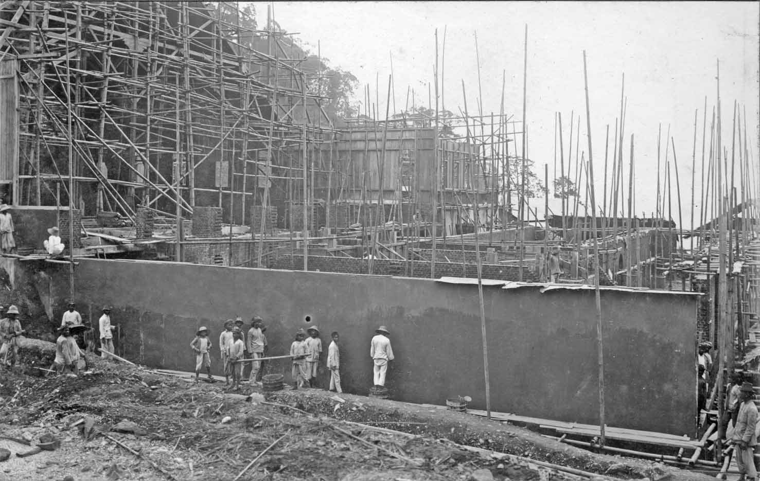
Page 33
Dubbeltorens in opbouw
Februari 1921
The construction in front is for housing the antenna-extension tuning. The magnetic- and electrical field strength can reach huge levels (technically the Poulsen 'grote Boog' was intended to radiate 2.4 MW antenna power, which value later was reduced to a lower level; owing to a series of practical reasons. However, its environment can be highly unhealthy! The antenna feeding voltage can reach 250,000 V ac (the antenna constituted a 'capacitive load'). Therefore the wooden construction was to built with great care. At some places even the nails which were used for fitting the construction together could be heated up to a dangerous level. Please, bear in mind, that the frequency versus wave-length is highly un-favourable. We consider, for this example, a transmitter frequency of 16 kHz. We know that: c = λƒ → λ = c /ƒ → λ = 300,000,000 / 16,000 = 18,750 m. The wave-length is thus 18.75 km. The section of the antenna that really radiates - is the section that runs from the antenna tuner upwards to the horizontal group of parallel wires. Earlier we have noticed: that the parallel wires in the canyon by itself does not (really) radiate, its only function is to act as a capacitance against ground; as to increase the antenna current at the beginning of the antenna system. When the current flows in the canyon back to the antenna-tuner, then this current was to be delivered once by the antenna tuner. We generally consider the antenna current as the most effective means of radiating EM fields. Theoretically, at λ / 0.6 the E/H ratio has reached the value of 120 π or 377 Ω (which is the impedance of free space). It has to be said, though, that the radiation pattern would have been different when the parallel antenna wires, inside the canyon, would have not been short in respect to λ. For greater wire lengths such a system gets directive properties. However, in this case it did not have (just over 2 km versus 18.75 km).
Maart 1921
Dubbeltoren in opbouw
Viewing the right-hand side antenna tower under construction. Please notice also the clouds hanging in the canyon. Living and working at Malabar was often quite unpleasant for most days of the year. Particularly in the wet seasons. Klaas Dijkstra once recorded, that it was officially prohibited that, in his own living place (a few hundred metres from the station building), an electrical stove was used! Consequently, they had to cope with a cold and wet house; where drying was sometimes rather difficult. Have you ever slept in a clammy bed? Those familiar, do know what moist means!
Maart 1921
The clouds are hanging rather low in the canyon.
Maart 1921
It might show the outlet of the turbines.
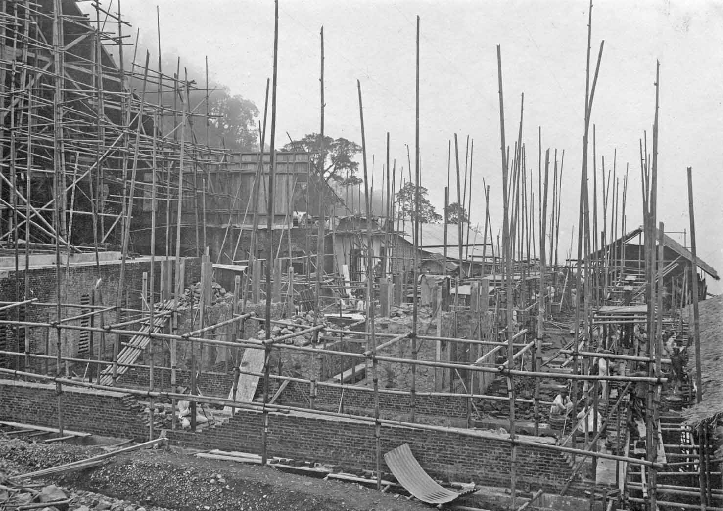
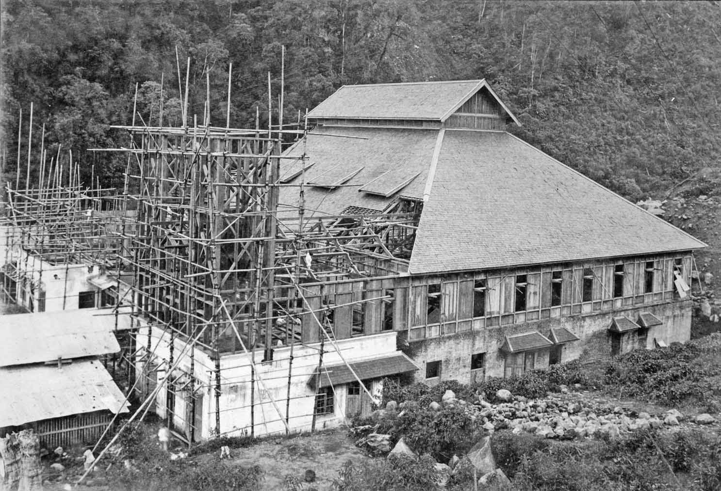
Page 34
Afbouwen grote hal

Maart 1921
Viewing the main station hall with antenna towers progressing from the west. On the right-hand side is the canyon entrance.

Maart 1921
Afbouwen grote hal.
I believe, that the foundation in front was meant for the building extension as to accommodate the Telefunken 'machinezender'.

Maart 1921
On our right-hand side is the eastern side of the Malabar canyon.
Page 35
Afvoergoot

11 Mei 1921
The water of this stream eventually will reach the Bandung high Valley.

11 Mei 1921
Eerste dubbeltoren klaar
The main hall more or less ready including the outside construction of the right-hand side antenna tower. It never before appeared in my mind: but is the far left-hand side tower meant for the Telefunken transmitter system or both?
The Telefunken transmitter operated somewhere in the 40 kHz spectrum. Its antenna ran about parallel to the big canyon antenna for the Poulsen spark-gap transmitter (de boog). It is known, that the parallel wire system for the Telefunken transmitter was shorter than for the Dr. de Groot's transmitter. The Telefunken antenna arrangement might have possessed a better efficiency.

11 Mei 1921
Grote hal gereed
The main transmitter hall being ready, but the eastern section was still under construction. because its planning originated from a later date (a directive by the Dutch Government)
Page 36
Uitbreiding

11 Mei 1921
Laying the fundaments for the the extension hall for the Telefunken transmitter. Viewing in the distance the Bandung high Valley.

11 Mei 1921
What the purpose of the squares in front was we don't know.

11 Mei 1921
A probably temporarily corridor fit with high voltage provisions
Or:
Please also consider the next photo instantly. Because the marble plate mounted the the tube frame is the backside of the next picture!
Page 37

11 Mai 1921
Schakelinstallatie
You might not instantly grasp the combination of this- and the foregoing image, but the right-hand side of the previous photo constitute the backside of this marble panel! Maybe the previous photo was taken a bit earlier so that the top panels at the previous photo were not yet being mounted (fit).
Finish of page 27 up to 37
Please continue with: page 38
To continue please return to: Bouw Radio Zendstation Malabar
Edited by: Arthur O. Bauer
Please return to, or proceed with: Dutch Indies PTT
![]()