
TU 50
Triode TU50 (TU 50)
Made by Fernseh AG
Employed in the German Tonne transmitter - the aircraft TV camera transmitter
Please notice the British post war report BIOS 867:
Television Development and Application in Germany
This valve type was a design of Fernseh AG, this company also produced it.

According this information, we may estimate that it was accepted or had been produced on 7 February 1945; carrying serial- or production number 1302. We may consider 1,5 standing for a filament voltage of 1.5 V
Whilst according information found on the web, and that aren't many - it should have been 1.4 V
According FTZ 1950 Heft 8: Über die Entwicklung der Fernsehtechnik bei der Fernseh G.m.b.H. 1935 - 1945 page 312:
This valve type operated at about 70 cm (≈ 428 MHz)
My first thought was - that it concerned a Barkhausen-Kurz type valve, but this apparently isn't correct.

The flat Ni strip actually is the grid-holder or fixer
The likely carbon anode has a triangle shape
The two top connections being the filament
The two connections on either side of the valve were meant for matching onto a Lecher-line system.
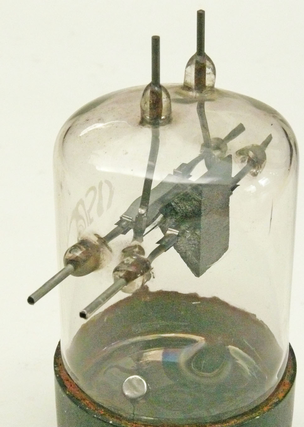
The triangle shaped anode block is well visible
Please look closely at the very thin spiral like construction around the central filament. This constitute the triode grid.
As to cope at rather high frequencies one needs short transit delays between the cathode and anode.
The grid in this valve is not spiral shaped - though, consists of a range of U-shaped parallel wires kept fixed by means of a flat Ni grid-wire-holder.
My first thought - that it might have concerned a Barkhausen-Kurz valve type isn't strange, because there the grid is taking the burden of energy dissipation, whereas the anode is only acting as an electrons reflector; where the electrons do not arrive, owing to the negative charge against the valve grid potential. Similar technique was later being used within reflex klystrons. Although, there they did not apply a grid though a resonant cavity. In the B-K concept the outside connected resonant circuitry is determining the signal frequency. The downside of a B-K valve type, is, that the grid is acting as an anode, hence: is also dissipating the valve loss. Therefore, hardly HF power passing 20 à 30 W can be generated continuously.
By the way, the application of a carbon anode has a great advantage, as it produces minimal secondary (electron) emission.
Why?
Because - the secondary emitting electrons being (mainly) bounced- and absorbed inside the small monocular-carbon-structure-holes.
Please notice also the new modulator valve DH 7
![]()